SECTION 2: ASSEMBLING YOUR SNOW THROWER
NOTE: Any reference in this manual to the left or right side of the snow thrower is observed from the operator’s position.
Unpacking
•Remove staples from the top, sides, and ends of the shipping crate.
•Set panels aside to avoid tire punctures or personal injury.
•Remove and discard plastic bag that covers unit.
•Roll the unit out of the crate.
•Check the crate thoroughly for loose parts before discarding.
Loose Parts
•The augers are secured to the auger shaft with two shear bolts and hex lock nuts. If you hit a foreign object or ice jam, the snow thrower is designed so that the bolts may shear. Two replacement shear bolts and nuts are provided for your convenience. Store in a safe place until needed. See Figure 1.
Shear Bolts |
| Hex Lock |
|
| |
|
| Nuts |
Figure 1
IMPORTANT: NEVER replace the auger shear bolts with standard hex bolts. Any damage to the auger gearbox or other components from standard hex bolts will not be covered by your snow thrower’s warranty.
Assembling Handle
WARNING: Disconnect the spark plug wire and ground it against the engine to prevent unintended starting.
IMPORTANT: Make any final adjustments, as instructed later on in this section, before operating your snow thrower. Failure to follow these instructions may cause damage to the snow thrower.
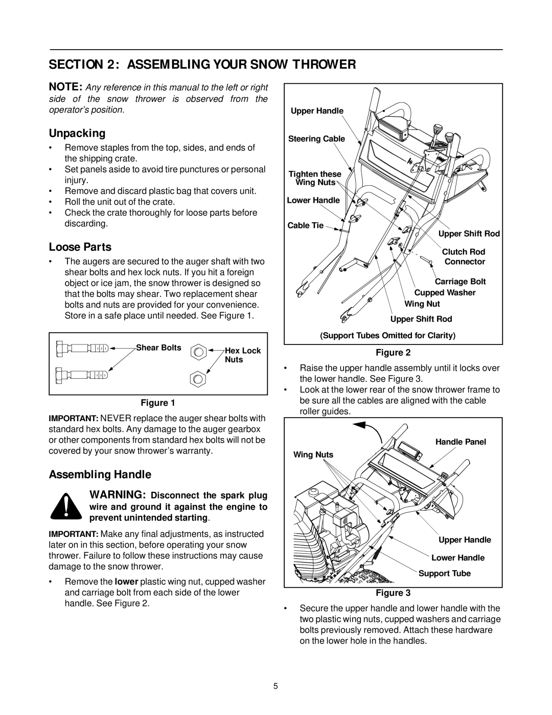
•Remove the lower plastic wing nut, cupped washer and carriage bolt from each side of the lower handle. See Figure 2.
Upper Handle |
Steering Cable |
Tighten these |
Wing Nuts |
Lower Handle |
Cable Tie |
Upper Shift Rod |
Clutch Rod |
Connector |
Carriage Bolt |
Cupped Washer |
Wing Nut |
Upper Shift Rod |
(Support Tubes Omitted for Clarity) |
Figure 2
•Raise the upper handle assembly until it locks over the lower handle. See Figure 3.
•Look at the lower rear of the snow thrower frame to be sure all the cables are aligned with the cable roller guides.
Handle Panel |
Wing Nuts |
Upper Handle |
Lower Handle |
Support Tube |
Figure 3
•Secure the upper handle and lower handle with the two plastic wing nuts, cupped washers and carriage bolts previously removed. Attach these hardware on the lower hole in the handles.
5