SECTION 8: MAKING ADJUSTMENTS
WARNING: Disconnect the spark plug wire(s) and ground against the engine before performing any adjustments, repairs or maintenance.
LEVELING THE DECK
The sides of the deck should be the same distance from the ground. The front of the deck should be 1/4" to 3/8" lower than the rear of the deck. If adjustment is required, refer to “Leveling the Deck” in Assembly Instructions.
Speed |
|
|
|
|
Control |
|
|
|
|
Lever | Rear Speed | |||
| Control Link | |||
|
|
| Pedal | |
| Cotter Pins |
|
|
|
| Flat Washers |
|
|
|
| Pins | Front Speed | ||
| Control Link | |||
|
| |||
|
|
| Point on | |
|
|
|
| Bracket |
|
|
|
| 3/4" Shim |
|
|
|
| |
Variable Speed
Torque Bracket
Assembly
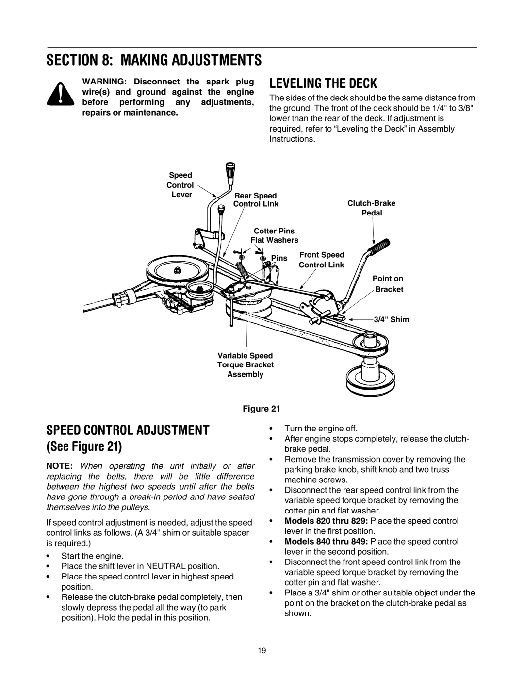
Figure 21
SPEED CONTROL ADJUSTMENT (See Figure 21)
NOTE: When operating the unit initially or after replacing the belts, there will be little difference between the highest two speeds until after the belts have gone through a
If speed control adjustment is needed, adjust the speed control links as follows. (A 3/4" shim or suitable spacer is required.)
•Start the engine.
•Place the shift lever in NEUTRAL position.
•Place the speed control lever in highest speed position.
•Release the
•Turn the engine off.
•After engine stops completely, release the clutch- brake pedal.
•Remove the transmission cover by removing the parking brake knob, shift knob and two truss machine screws.
•Disconnect the rear speed control link from the variable speed torque bracket by removing the cotter pin and flat washer.
•Models 820 thru 829: Place the speed control lever in the first position.
•Models 840 thru 849: Place the speed control lever in the second position.
•Disconnect the front speed control link from the variable speed torque bracket by removing the cotter pin and flat washer.
•Place a 3/4" shim or other suitable object under the point on the bracket on the
19