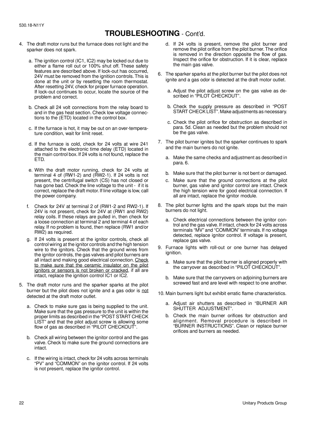
D2CG300, D2CE specifications
The York D2CE and D2CG series represent cutting-edge advancements in energy-efficient chiller technology, specifically designed to optimize performance in a variety of commercial and industrial applications. These chillers are known for their ability to deliver reliable cooling while minimizing energy consumption, making them a preferred choice for businesses aiming to reduce their carbon footprint and operational costs.One of the standout features of the York D2CE and D2CG chillers is their utilization of advanced scroll compressor technology. This technology not only enhances the reliability of the systems but also significantly improves energy efficiency, allowing for lower operational costs. The chillers are built to provide high efficiency across a diverse range of operating conditions, ensuring consistent performance during peak loads.
The D2CE series, designed primarily for air-cooled applications, benefits from a compact and modular design, allowing for flexible installation in tight spaces. Additionally, its quiet operation makes it suitable for use in noise-sensitive environments, such as healthcare facilities and educational institutions. The model is equipped with microprocessor controls that facilitate precise temperature regulation and system diagnostics, ensuring optimal operation.
Conversely, the D2CG series focuses on water-cooled applications, featuring robust construction that accommodates higher cooling capacities. This model also includes advanced heat exchanger technology, which maximizes heat transfer efficiency. The D2CG’s intelligent controls not only help in energy management but also provide remote monitoring capabilities, allowing facility managers to analyze performance and troubleshoot issues from anywhere.
Both models utilize environmentally friendly refrigerants, aligning with global regulations and promoting sustainability. Enhanced filtration options are available, enabling the units to maintain high indoor air quality by minimizing dust and other pollutants.
In addition to their energy-saving attributes, the York D2CE and D2CG chillers are designed for ease of maintenance, with accessible components and modular parts that simplify service procedures. This, coupled with their durable construction, leads to greater longevity and reliability in operation.
In summary, the York D2CE and D2CG chillers are leading examples of modern HVAC engineering, combining efficiency, flexibility, and sustainability. Their innovative technologies and thoughtful design make them an excellent addition to any facility looking to enhance its cooling systems while adhering to environmental standards.
