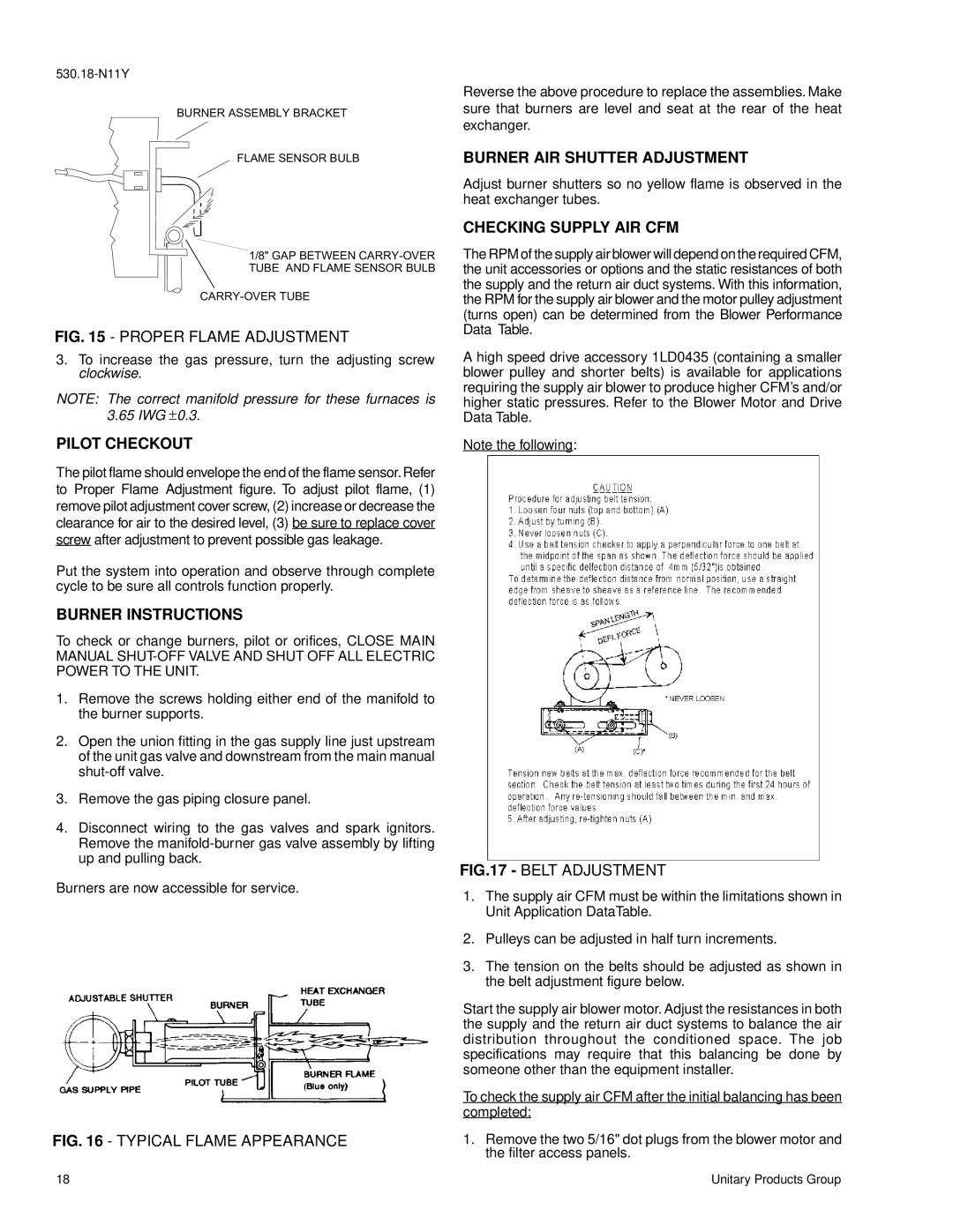
FIG. 15 - PROPER FLAME ADJUSTMENT

530.18-N11Y

￿￿￿￿￿￿￿￿￿￿￿￿￿￿￿￿￿￿￿￿￿￿￿

￿￿￿￿￿￿￿￿￿￿￿￿￿￿￿￿￿

￿￿￿￿￿￿￿￿￿￿￿￿￿￿￿￿￿￿￿￿￿￿￿￿￿￿￿￿

￿￿￿￿￿￿￿￿￿￿￿￿￿￿￿￿￿￿￿￿￿￿￿￿￿￿￿

￿￿￿￿￿￿￿￿￿￿￿￿￿￿￿

FIG. 15 - PROPER FLAME ADJUSTMENT

3.To increase the gas pressure, turn the adjusting screw clockwise.

NOTE: The correct manifold pressure for these furnaces is 3.65 IWG ± 0.3.

PILOT CHECKOUT

Reverse the above procedure to replace the assemblies. Make sure that burners are level and seat at the rear of the heat exchanger.

BURNER AIR SHUTTER ADJUSTMENT

Adjust burner shutters so no yellow flame is observed in the heat exchanger tubes.

CHECKING SUPPLY AIR CFM

The RPM of the supply air blower will depend on the required CFM, the unit accessories or options and the static resistances of both the supply and the return air duct systems. With this information, the RPM for the supply air blower and the motor pulley adjustment (turns open) can be determined from the Blower Performance Data Table.

A high speed drive accessory 1LD0435 (containing a smaller blower pulley and shorter belts) is available for applications requiring the supply air blower to produce higher CFM’s and/or higher static pressures. Refer to the Blower Motor and Drive Data Table.

Note the following:

The pilot flame should envelope the end of the flame sensor.Refer to Proper Flame Adjustment figure. To adjust pilot flame, (1) remove pilot adjustment cover screw, (2) increase or decrease the clearance for air to the desired level, (3) be sure to replace cover screw after adjustment to prevent possible gas leakage.

Put the system into operation and observe through complete cycle to be sure all controls function properly.

BURNER INSTRUCTIONS

To check or change burners, pilot or orifices, CLOSE MAIN MANUAL SHUT-OFF VALVE AND SHUT OFF ALL ELECTRIC POWER TO THE UNIT.

1.Remove the screws holding either end of the manifold to the burner supports.

2.Open the union fitting in the gas supply line just upstream of the unit gas valve and downstream from the main manual shut-off valve.

3.Remove the gas piping closure panel.

4.Disconnect wiring to the gas valves and spark ignitors. Remove the manifold-burner gas valve assembly by lifting up and pulling back.

Burners are now accessible for service.

FIG. 16 - TYPICAL FLAME APPEARANCE

FIG.17 - BELT ADJUSTMENT

1.The supply air CFM must be within the limitations shown in Unit Application DataTable.

2.Pulleys can be adjusted in half turn increments.

3.The tension on the belts should be adjusted as shown in the belt adjustment figure below.

Start the supply air blower motor. Adjust the resistances in both the supply and the return air duct systems to balance the air distribution throughout the conditioned space. The job specifications may require that this balancing be done by someone other than the equipment installer.

To check the supply air CFM after the initial balancing has been completed:

1.Remove the two 5/16" dot plugs from the blower motor and the filter access panels.

18

Unitary Products Group

Page 18
Image 18
York D2CE Proper Flame Adjustment, Pilot Checkout, Burner Air Shutter Adjustment, Checking Supply Air Cfm, Belt Adjustment

D2CG300, D2CE specifications

The York D2CE and D2CG series represent cutting-edge advancements in energy-efficient chiller technology, specifically designed to optimize performance in a variety of commercial and industrial applications. These chillers are known for their ability to deliver reliable cooling while minimizing energy consumption, making them a preferred choice for businesses aiming to reduce their carbon footprint and operational costs.

One of the standout features of the York D2CE and D2CG chillers is their utilization of advanced scroll compressor technology. This technology not only enhances the reliability of the systems but also significantly improves energy efficiency, allowing for lower operational costs. The chillers are built to provide high efficiency across a diverse range of operating conditions, ensuring consistent performance during peak loads.

The D2CE series, designed primarily for air-cooled applications, benefits from a compact and modular design, allowing for flexible installation in tight spaces. Additionally, its quiet operation makes it suitable for use in noise-sensitive environments, such as healthcare facilities and educational institutions. The model is equipped with microprocessor controls that facilitate precise temperature regulation and system diagnostics, ensuring optimal operation.

Conversely, the D2CG series focuses on water-cooled applications, featuring robust construction that accommodates higher cooling capacities. This model also includes advanced heat exchanger technology, which maximizes heat transfer efficiency. The D2CG’s intelligent controls not only help in energy management but also provide remote monitoring capabilities, allowing facility managers to analyze performance and troubleshoot issues from anywhere.

Both models utilize environmentally friendly refrigerants, aligning with global regulations and promoting sustainability. Enhanced filtration options are available, enabling the units to maintain high indoor air quality by minimizing dust and other pollutants.

In addition to their energy-saving attributes, the York D2CE and D2CG chillers are designed for ease of maintenance, with accessible components and modular parts that simplify service procedures. This, coupled with their durable construction, leads to greater longevity and reliability in operation.

In summary, the York D2CE and D2CG chillers are leading examples of modern HVAC engineering, combining efficiency, flexibility, and sustainability. Their innovative technologies and thoughtful design make them an excellent addition to any facility looking to enhance its cooling systems while adhering to environmental standards.