Manuals
/
York
/
Household Appliance
/
Air Conditioner
York
D2EB Clearances, Duct Work, Filters, Condensate Drain, Service Access, Thermostat
Models:
D2EB
1
3
16
16
Download
16 pages
40.19 Kb
1
2
3
4
5
6
7
8
Page 3
Image 3
Page 2
Page 4
Page 3
Image 3
Page 2
Page 4
Contents
REFERENCE
INSTALLATION INSTRUCTION
REPLACEMENT PARTS
GENERAL
LOCATION
INSTALLATION
LIMITATIONS
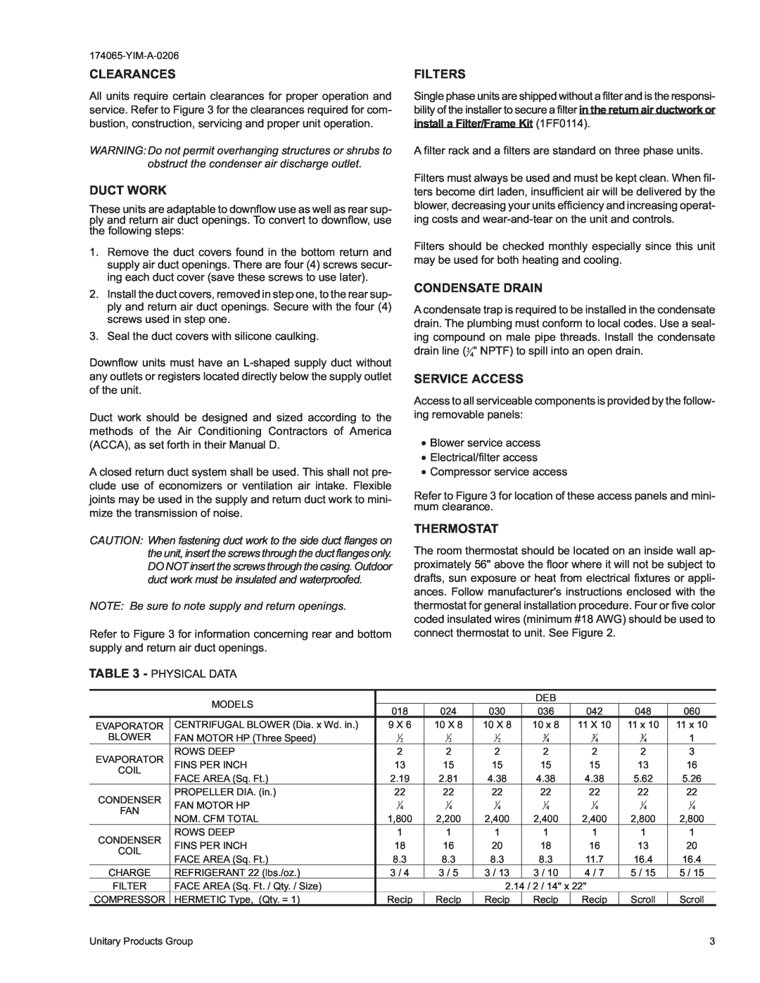
TABLE 1 - UNIT APPLICATION DATA
FILTERS
SERVICE ACCESS
CLEARANCES
DUCT WORK
POWER WIRING
POWER AND CONTROL WIRING
FIG. 2 - TYPICAL FIELD WIRING DIAGRAM
CONTROL WIRING
TABLE 4 - ELECTRICAL DATA BASIC UNIT
TABLE 5 - ELECTRICAL DATA COOLING / ELECTRIC HEAT
DEB Coil Delta P vs Airflow
Checking Supply Air CFM
174065-YIM-A-0206
174065-YIM-A-0206
14 BACK
FIG. 3 - DIMENSIONS AND CLEARANCES
FRONT
FRONT
SEQUENCE OF OPERATION
Cooling
Heating
NORMAL MAINTENANCE
MAINTENANCE
SEE DETAIL B
DETAIL A
Unitary Products Group
TYPICAL WIRING DIAGRAM LEGEND
TYPICAL WIRING DIAGRAM NOTES
174065-YIM-A-0206
Unitary Products Group
174065-YIM-A-0206
174065-YIM-A-0206
Unitary Products Group
5005 York Drive, Norman Oklahoma
Supersedes Nothing
Top
Page
Image
Contents