The cooling section is a complete factory package utilizing an air-cooled condenser. The system is factory-charged with Refrigerant-22.
The scroll compressor is hermetically sealed and internally sprung. The scroll compressors have inherent (internal) protection. If there is an abnormal temperature rise in the scroll compressor, the protector will open to shut down the scroll compressor.
COOLING SEQUENCE OF OPERATION
Single-Stage Cooling: When the thermostat calls for “cooling”, “R” is closed to “G” and “Y1" (wiring schematic) which completes the low voltage control circuit, immediately energizing the scroll compressor, condenser fan motor and blower motor simultaneously.
Two-Stage Cooling: A two-stage cooling thermostat may be used if the unit has an economizer. First-stage cooling is provided by the economizer - if the outdoor air enthalpy is acceptable, and second-stage cooling is provided by the scroll compressor. Jumper wire J1 must be removed. Refer to the unit wiring diagram.
After the thermostat is satisfied and opens, all components will stop simultaneously.
CONTINUOUS BLOWER - Continuous blower operation is possible by closing the R to G circuit on the thermostat.
SAFETY CONTROLS (Cooling)
The refrigerant system is equipped with the following safety controls:
1.A Suction Line Freezestat to protect against low evaporator temperatures due to a low air flow or a low return air temperature.
2.A High Pressure Cutout Switch to protect against excessive discharge pressures due to a blocked condenser coil or a condenser motor failure.
3.A Low Pressure Switch to protect against loss of refrigerant charge.
If either one of the above safety controls opens, the refrigerant system will be locked out. The lock out of the system can be reset by opening the 24V circuit either at the room thermostat or at the unit disconnect.
HEATING SEQUENCE OF OPERATION
The following sequence describes the operation of the gas heat section.
CONTINUOUS BLOWER: With the room thermostat switch set to “ON”, the supply air blower will operate continuously. The normally closed blower interlock relay contact “K3-1" provides 24 volt power to the blower relay ”BR". The “BR” power contacts close and the blower motor operates.
INTERMITTENT BLOWER: With the room thermostat system switch set to the “AUTO” or “HEAT” position and the fan switch set to “AUTO”, the supply air blower will operate after the room thermostat calls for heat and the air in the gas heat compartment has achieved a pre-set temperature.
When “TH1" on the thermostat closes, the draft motor relay ”DMR" or "DMC" is energized. The “DMR” or "DMC" power contacts close which energizes the line voltage draft motor. As the speed of the draft motor reaches approximately 2500 RPM, the centrifugal switch contact “CS” located on the end of the draft motor shaft closes to power the ignition control “IC”.
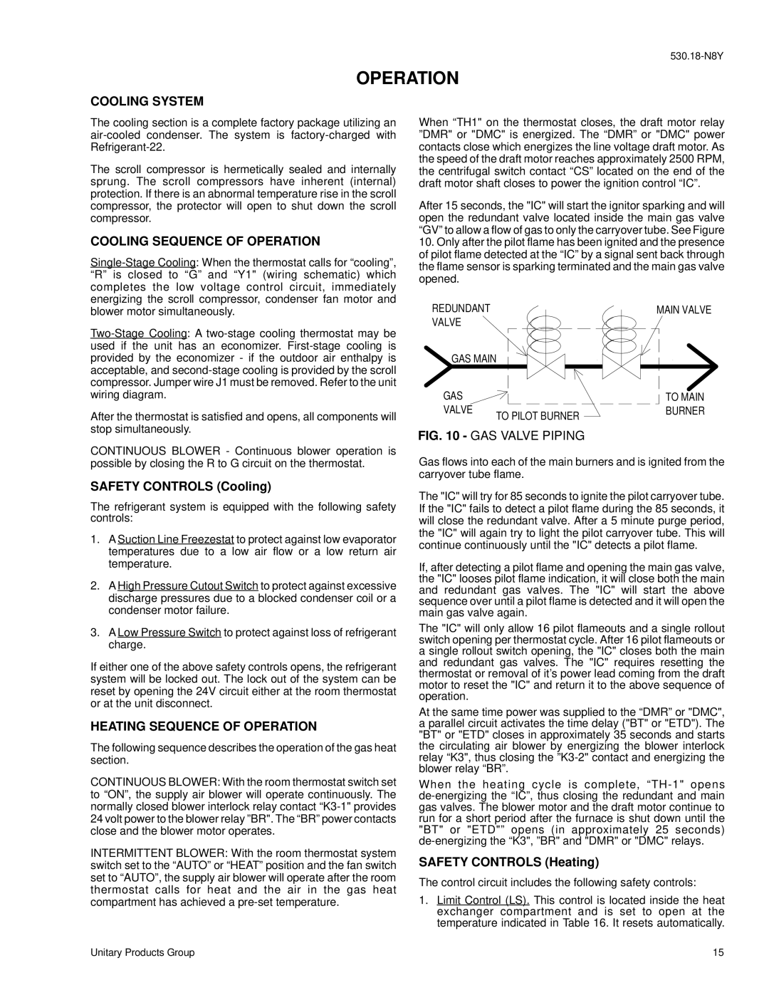
After 15 seconds, the "IC" will start the ignitor sparking and will open the redundant valve located inside the main gas valve “GV” to allow a flow of gas to only the carryover tube. See Figure
10.Only after the pilot flame has been ignited and the presence of pilot flame detected at the “IC” by a signal sent back through the flame sensor is sparking terminated and the main gas valve opened.
REDUNDANT | | MAIN VALVE |
VALVE | | |
GAS MAIN | |
GAS | | TO MAIN |
VALVE | TO PILOT BURNER | BURNER |
| |
FIG. 10 - GAS VALVE PIPING
Gas flows into each of the main burners and is ignited from the carryover tube flame.
The "IC" will try for 85 seconds to ignite the pilot carryover tube. If the "IC" fails to detect a pilot flame during the 85 seconds, it will close the redundant valve. After a 5 minute purge period, the "IC" will again try to light the pilot carryover tube. This will continue continuously until the "IC" detects a pilot flame.
If, after detecting a pilot flame and opening the main gas valve, the "IC" looses pilot flame indication, it will close both the main and redundant gas valves. The "IC" will start the above sequence over until a pilot flame is detected and it will open the main gas valve again.
The "IC" will only allow 16 pilot flameouts and a single rollout switch opening per thermostat cycle. After 16 pilot flameouts or a single rollout switch opening, the "IC" closes both the main and redundant gas valves. The "IC" requires resetting the thermostat or removal of it’s power lead coming from the draft motor to reset the "IC" and return it to the above sequence of operation.
At the same time power was supplied to the “DMR” or "DMC", a parallel circuit activates the time delay ("BT" or "ETD"). The "BT" or "ETD" closes in approximately 35 seconds and starts the circulating air blower by energizing the blower interlock relay “K3", thus closing the ”K3-2" contact and energizing the blower relay “BR”.
When the heating cycle is complete, “TH-1" opens de-energizing the “IC”, thus closing the redundant and main gas valves. The blower motor and the draft motor continue to run for a short period after the furnace is shut down until the "BT" or "ETD"” opens (in approximately 25 seconds) de-energizing the “K3", ”BR" and "DMR" or "DMC" relays.
SAFETY CONTROLS (Heating)
The control circuit includes the following safety controls:
1.Limit Control (LS). This control is located inside the heat exchanger compartment and is set to open at the temperature indicated in Table 16. It resets automatically.