UnitaryProducts | ThermostatChart |
|
|
|
|
|
|
|
|
|
|
|
|
|
|
|
|
|
|
|
|
|
|
|
|
|
|
|
AC1 |
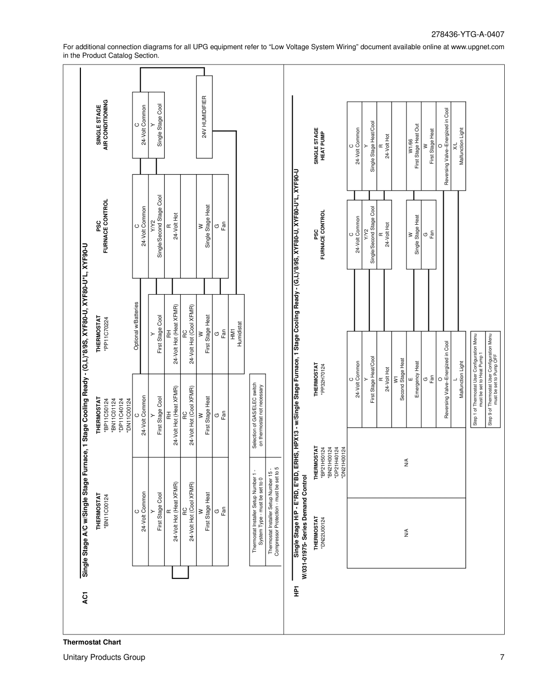
| Single Stage A/C w/Single Stage Furnace, 1 Stage Cooling Ready - (G,L)*8/9S, |
|
|
|
|
|
|
|
|
| |||||||||||||||||
|
|
|
|
|
|
|
|
|
|
|
| |||||||||||||||||
|
|
|
|
|
| THERMOSTAT |
|
|
| THERMOSTAT | THERMOSTAT |
| PSC |
|
| SINGLE STAGE | ||||||||||||
|
|
|
|
|
| *BN11C00124 |
|
|
| *BP11C50124 | *PP11C70224 |
| FURNACE CONTROL |
|
| AIR CONDITIONING | ||||||||||||
|
|
|
|
|
|
|
|
|
|
| *BN11C01124 |
|
|
|
|
|
|
|
|
|
|
|
|
|
|
| ||
Group |
|
|
|
|
|
|
|
| *DP11C40124 |
|
|
|
|
|
| |||||||||||||
|
|
|
|
|
|
|
|
|
|
|
|
|
| |||||||||||||||
|
|
|
|
|
|
|
|
|
|
| *DN11C00124 |
|
|
|
|
|
|
|
|
|
|
|
|
|
|
| ||
|
|
|
|
|
| C |
|
|
|
| C |
| Optional w/Batteries |
| C |
|
|
| C |
|
|
| ||||||
|
|
|
|
|
|
|
|
|
|
|
|
|
|
|
|
|
|
|
|
|
|
|
|
|
|
|
|
|
|
|
|
|
|
| Y |
|
|
|
| Y |
| Y |
|
| Y/Y2 |
|
|
| Y |
|
|
| |||||
|
|
|
|
|
| First Stage Cool |
|
|
| First Stage Cool |
| First Stage Cool |
|
| Single/Second Stage Cool |
|
| Single Stage Cool |
|
|
| |||||||
|
|
|
|
|
|
|
|
|
|
|
|
|
|
|
|
|
|
|
|
|
|
|
|
|
|
|
|
|
|
|
|
|
|
| R |
|
|
|
| RH |
| RH |
|
| R |
|
|
|
|
|
|
|
|
| |||
|
|
|
|
|
|
|
|
|
|
|
|
|
|
|
|
|
|
|
|
| ||||||||
|
|
|
|
|
|
|
|
|
|
|
|
|
|
|
|
|
|
|
|
|
|
|
|
|
|
|
|
|
|
|
|
|
|
| RC |
|
|
|
| RC |
| RC |
|
|
|
|
|
|
|
|
|
|
|
|
| ||
|
|
|
|
|
|
|
|
|
|
|
|
|
|
|
|
|
|
|
|
|
|
| ||||||
|
|
|
|
|
|
|
|
|
|
|
|
|
|
|
|
|
|
|
|
|
|
|
|
|
|
|
|
|
|
|
|
|
|
| W |
|
|
|
| W |
| W |
|
| W |
|
| 24V HUMIDIFIER |
|
| |||||||
|
|
|
|
|
| First Stage Heat |
|
|
| First Stage Heat |
| First Stage Heat |
|
| Single Stage Heat |
|
|
|
| |||||||||
|
|
|
|
|
|
|
|
|
|
|
|
|
|
|
|
|
|
|
|
| ||||||||
|
|
|
|
|
|
|
|
|
|
|
|
|
|
|
|
|
|
|
|
|
|
|
|
|
|
|
|
|
|
|
|
|
|
| G |
|
|
|
| G |
| G |
|
| G |
|
|
|
|
|
|
|
|
| |||
|
|
|
|
|
| Fan |
|
|
|
| Fan |
| Fan |
|
| Fan |
|
|
|
|
|
|
|
|
| |||
|
|
|
|
|
|
|
|
|
|
|
|
|
|
|
|
|
|
|
|
|
|
|
|
|
|
|
|
|
|
|
|
|
|
|
|
|
|
|
|
|
|
| HM1 |
|
|
|
|
|
|
|
|
|
|
|
|
| |
|
|
|
|
|
|
|
|
|
|
|
|
|
| Humidistat |
|
|
|
|
|
|
|
|
|
|
|
|
| |
|
|
|
|
|
|
|
|
|
|
|
|
|
|
|
|
|
|
|
|
|
|
|
|
|
|
| ||
|
|
|
|
|
|
|
|
|
|
|
|
|
|
|
|
|
|
|
|
|
|
|
|
|
| |||
|
|
|
|
|
| Thermostat Installer Setup Number 1 - |
| Selection of GAS/ELEC switch |
|
|
|
|
|
|
|
|
|
|
|
|
|
|
|
| ||||
|
|
|
|
|
| System Type - must be set to 0 |
| on thermostat not necessary |
|
|
|
|
|
|
|
|
|
|
|
|
|
|
|
| ||||
|
|
|
|
|
|
|
|
|
|
|
|
|
|
|
|
|
|
|
|
|
|
|
|
|
|
|
| |
|
|
|
|
|
| Thermostat Installer Setup Number 15 - |
|
|
|
|
|
|
|
|
|
|
|
|
|
|
|
|
|
|
|
| ||
|
|
|
|
|
| Compressor Protection - must be set to 5 |
|
|
|
|
|
|
|
|
|
|
|
|
|
|
|
|
|
|
|
| ||
|
|
|
|
|
|
|
|
|
|
|
|
|
|
|
|
|
|
|
|
|
|
|
|
|
|
|
|
|
|
| HP1 |
|
|
|
| ||||||||||||||||||||||
|
|
|
|
| Single Stage H/P - E*RD, E*BD, ERHS, HPX13 - w/Single Stage Furnace, 1 Stage Cooling Ready - (G,L)*8/9S, |
| ||||||||||||||||||||||
|
|
|
|
|
|
|
|
|
|
|
|
|
|
|
|
|
|
|
|
|
|
| ||||||
|
|
|
|
|
| THERMOSTAT | THERMOSTAT |
| THERMOSTAT |
| PSC |
| SINGLE STAGE | |||||||||||||||
|
|
|
|
|
| *DN22U00124 | *BP21H50124 |
| *PP32H70124 |
| FURNACE CONTROL |
| HEAT PUMP | |||||||||||||||
|
|
|
|
|
|
|
| *BN21H00124 |
|
|
|
|
|
|
|
|
|
|
|
|
|
|
|
|
|
| ||
|
|
|
|
|
|
|
| *DP21H40124 |
|
|
|
|
|
|
|
|
|
|
|
|
|
|
|
|
|
| ||
|
|
|
|
|
|
|
| *DN21H00124 |
|
|
|
|
|
|
|
|
|
|
|
|
|
|
|
|
|
| ||
|
|
|
|
|
|
|
|
|
|
|
| C |
|
|
|
| C |
|
|
| C |
|
| |||||
|
|
|
|
|
|
|
|
|
|
|
|
|
|
|
|
|
| |||||||||||
|
|
|
|
|
|
|
|
|
|
|
|
|
|
|
|
|
|
|
|
|
|
|
| |||||
|
|
|
|
|
|
|
|
|
|
|
| Y |
|
|
|
| Y/Y2 |
|
|
| Y |
|
| |||||
|
|
|
|
|
|
|
|
|
|
|
| First Stage Heat/Cool |
|
| Single/Second Stage Cool |
|
| Single Stage Heat/Cool |
|
| ||||||||
|
|
|
|
|
|
|
|
|
|
|
|
|
|
|
|
|
|
|
|
|
|
|
| |||||
|
|
|
|
|
|
|
|
|
|
|
| R |
|
|
|
| R |
|
|
| R |
|
| |||||
|
|
|
|
|
|
|
|
|
|
|
|
|
|
|
|
|
|
|
|
| ||||||||
|
|
|
|
|
|
|
|
|
|
|
|
|
|
|
|
|
|
|
|
|
|
|
|
|
|
|
| |
|
|
|
|
|
|
|
|
|
|
|
| W1 |
|
|
|
|
|
|
|
|
|
|
|
|
|
|
| |
|
|
|
|
|
| N/A |
|
| N/A |
| Second Stage Heat |
|
|
|
|
|
|
|
|
|
|
|
|
| ||||
|
|
|
|
|
|
|
|
|
|
|
|
|
|
|
|
|
|
|
|
|
|
|
|
|
| |||
|
|
|
|
|
|
|
|
|
|
|
| E |
|
|
|
| W |
|
|
| W1/66 |
|
| |||||
|
|
|
|
|
|
|
|
|
|
|
| Emergency Heat |
|
| Single Stage Heat |
|
| First Stage Heat Out |
|
| ||||||||
|
|
|
|
|
|
|
|
|
|
|
|
|
|
|
|
|
|
|
|
|
|
|
| |||||
|
|
|
|
|
|
|
|
|
|
|
| G |
|
|
|
| G |
|
|
| W |
|
| |||||
|
|
|
|
|
|
|
|
|
|
|
| Fan |
|
|
|
| Fan |
|
| First Stage Heat |
|
|
|
|
| |||
|
|
|
|
|
|
|
|
|
|
|
|
|
|
|
|
|
|
|
|
|
|
|
| |||||
|
|
|
|
|
|
|
|
|
|
|
| O |
|
|
|
|
|
|
|
| O |
|
| |||||
|
|
|
|
|
|
|
|
|
|
|
| Reversing |
|
|
|
|
| Reversing |
|
|
|
|
| |||||
|
|
|
|
|
|
|
|
|
|
|
|
|
|
|
|
|
|
|
|
|
|
|
| |||||
|
|
|
|
|
|
|
|
|
|
|
| L |
|
|
|
|
|
|
|
| X/L |
|
| |||||
|
|
|
|
|
|
|
|
|
|
|
| Malfunction Light |
|
|
|
|
|
| Malfunction Light |
|
|
|
|
| ||||
|
|
|
|
|
|
|
|
|
|
|
|
|
|
|
|
|
|
|
|
|
|
|
|
|
| |||
|
|
|
|
|
|
|
|
|
|
|
|
|
|
|
|
|
|
|
|
|
|
|
|
| ||||
|
|
|
|
|
|
|
|
|
|
|
| Step 1 of Thermostat User Configuration Menu |
|
|
|
|
|
|
|
|
|
|
|
|
|
| ||
|
|
|
|
|
|
|
|
|
|
|
| must be set to Heat Pump 1 |
|
|
|
|
|
|
|
|
|
|
|
|
| |||
|
|
|
|
|
|
|
|
|
|
|
|
|
|
|
|
|
|
|
|
|
|
|
|
|
| |||
|
|
|
|
|
|
|
|
|
|
|
| Step 9 of Thermostat User Configuration Menu |
|
|
|
|
|
|
|
|
|
|
|
|
|
| ||
|
|
|
|
|
|
|
|
|
|
|
| must be set to Pump OFF |
|
|
|
|
|
|
|
|
|
|
|
|
| |||
7 |
|
|
|
|
|
|
|
|
|
|
|
|
|
|
|
|
|
|
|
|
|
|
|
|
|
|
|
|
|
|
|
|
|
|
|
|
|
|
|
|
|
|
|
|
|
|
|
|
|
|
|
|
|
|
|
| |
in the Product | For additional |
Catalog Section. | connection diagrams |
|