York PT9 warranty Filter Performance, Recommended Filter Sizes, Unit Clearances To Combustibles

Models: PT9

1 8
Download 8 pages 48.63 Kb
Page 4
Image 4

246782-YTG-B-0407

FILTER PERFORMANCE

The airflow capacity data published in the “Blower Perfor- mance” table listed above represents blower performance WITHOUT filters. To determine the approximate blower per- formance of the system, apply the filter drop value for the fil- ter being used or select an appropriate value from the “Filter Performance” table shown.

NOTE: The filter pressure drop values in the “Filter Perfor- mance” table shown are typical values for the type of filter listed and should only be used as a guideline. Actual pres- sure drop ratings for each filter type vary between filter manu- facturer.

RECOMMENDED FILTER SIZES

Input

CFM

Cabinet

Top Return

BTU/H

Size

Filter in


60

1200

B

(2) 14 x 20


80

1200

B

(2) 14 x 20


80

1600

C

(2) 14 x 20


100

2000

C

(2) 14 x 20


120

2000

D

(2) 14 x 20


NOTES:

1.Air velocity through throwaway type filters may not exceed 300 feet per minute. All velocities over this require the use of high velocity filters.

APPLYING FILTER PRESSURE DROP TO DETERMINE SYSTEM AIRFLOW

To determine the approximate airflow of the unit with a filter in place, follow the steps below:

1.Select the filter type.

2.Determine the External System Static Pressure (ESP) without the filter.

FILTER PERFORMANCE - PRESSURE DROP INCHES W.C.

3.Select a filter pressure drop from the table based upon the number of return air openings or return air opening size and add to the ESP from Step 3 to determine the total system static.

4.If total system static matches a ESP value in the airflow table (i.e. 0.20, 0.60, etc,) the system airflow corre- sponds to the intersection of the ESP column and Model/ Blower Speed row.

5.If the total system static falls between ESP values in the table (i.e. 0.58, 0.75, etc.), the static pressure may be rounded to the nearest value in the table determining the airflow using Step 5 or calculate the airflow by using the following example.

Example: For a 120,000 Btuh furnace operating on high speed blower, it is found that total system static is 0.58" w.c. To determine the system airflow, complete the following steps:

1.Obtain the airflow values at 0.50" & 0.60" ESP.

Airflow @ 0.50": 2152CFM

Airflow @ 0.60": 2042 CFM

2.Subtract the airflow @ 0.50" from the airflow @ 0.60" to obtain airflow difference.

2042 - 2152 = -110 CFM

Subtract the total system static from 0.50" and divide this difference by the difference in ESP values in the table, 0.60" - 0.50", to obtain a percentage.

(0.58 - 0.50) / (0.60 - 0.50) = 0.8

3.Multiply percentage by airflow difference to obtain airflow reduction.

(0.8) x (-110) = -88

4.Subtract airflow reduction value to airflow @ 0.50" to obtain actual airflow @ 0.58" ESP.

2152 - 88 = 2064

Airflow Range

Minimum


Filter Type


Opening Size

Disposable

Washable Fibers

Pleated


CFM

in2

In W.C.

In W.C.

In W.C.

0 - 750

230

0.01

0.01

0.15


751 - 1000

330

0.05

0.05

0.20


1001 - 1250

330

0.10

0.10

0.20


1251 - 1500

330

0.10

0.10

0.25


1501 - 1750

380

0.15

0.14

0.30


1751 - 2000

380

0.19

0.18

0.30


2001 & Above

463

0.19

0.18

0.30


UNIT CLEARANCES TO COMBUSTIBLES

Application

Top

Front

Rear

Left Side

Right Side

Flue

Floor/Bottom

Closet

Alcove

Attic

Line

In.

In.

In.

In.

In.

In.

In.

Contact


Downflow

1

3

0

0

0

0

1*

Yes

Yes

Yes

NA

Horizontal

0

3

0

1

1

0

0

Yes

Yes

Yes

Yes2

*Combustible floor base or air conditioning coil required for use on combustible floor.

4

Unitary Products Group
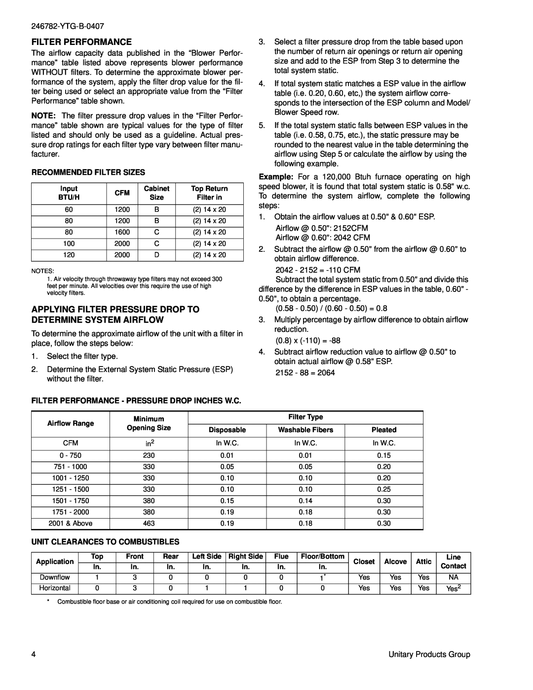
Page 4
Image 4
York PT9 Recommended Filter Sizes, Filter Performance - Pressure Drop Inches W.C, Unit Clearances To Combustibles