WR 180 specifications
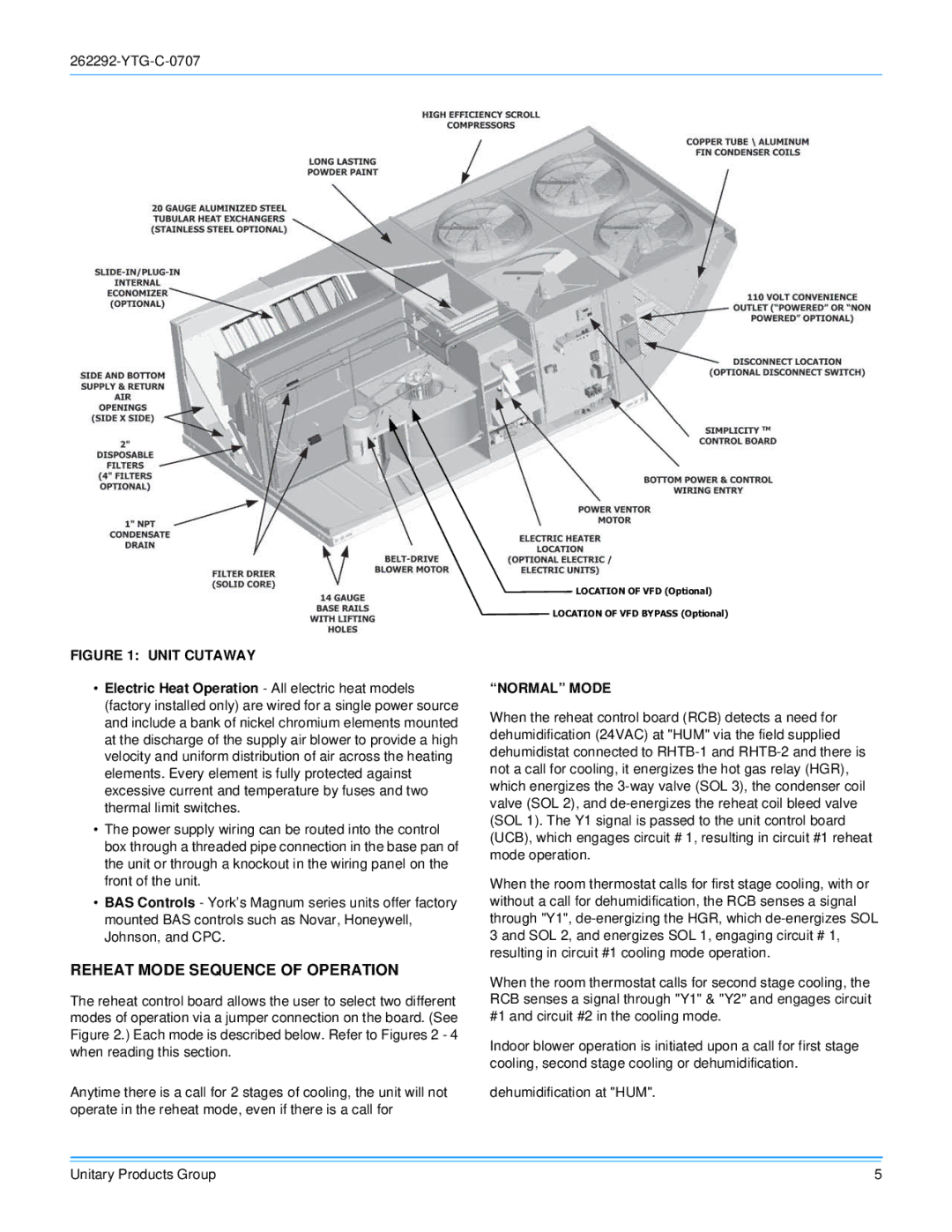
The York WR 180 is a state-of-the-art water-cooled chiller, renowned for its efficiency, flexibility, and reliability in various applications. Designed specifically for commercial and industrial use, the WR 180 stands out as an ideal solution for facilities requiring effective climate control, such as hotels, hospitals, shopping malls, and large office buildings.One of the primary features of the York WR 180 is its advanced chiller design, which incorporates variable speed technology. This allows the unit to adjust its cooling capacity based on the actual load demands of the building, leading to significant energy savings. By operating at variable speeds instead of a fixed rate, the chiller minimizes energy consumption during lower demand periods while maintaining optimal performance during peak loads.
The WR 180 also employs a reliable and efficient centrifugal compressor, which contributes to its high energy efficiency ratio (EER). This compressor is designed to provide robust cooling while operating quietly, making it suitable for environments where noise reduction is essential. Additionally, the unit features a microprocessor-based control system that offers sophisticated monitoring and control capabilities, allowing operators to fine-tune performance and enhance reliability.
Another notable characteristic of the York WR 180 is its environmentally friendly refrigerant options. The chiller can operate with refrigerants that have a low global warming potential (GWP), aligning with international regulations and environmental sustainability goals. This commitment to eco-friendly designs not only helps reduce the carbon footprint but also ensures compliance with industry standards.
In terms of installation and maintenance, the WR 180 is designed for user-friendliness. Its modular design simplifies transport and installation in various spaces, while easy-access components facilitate routine maintenance. The chiller also offers various connectivity options, enabling integration with building management systems for real-time monitoring and control.
Overall, the York WR 180 combines innovative design, cutting-edge technology, and eco-friendly practices, making it a top choice for industries seeking efficient and sustainable cooling solutions. Its impressive features, coupled with strong operational flexibility, position the WR 180 as a leader in the chiller market.

