STEP 1. Locate the assembly drawing for the version number printed on
the M1002 or M1002A circuit board to be serviced.
2.Remove all of the transistors coloured RED on the assembly drawing.
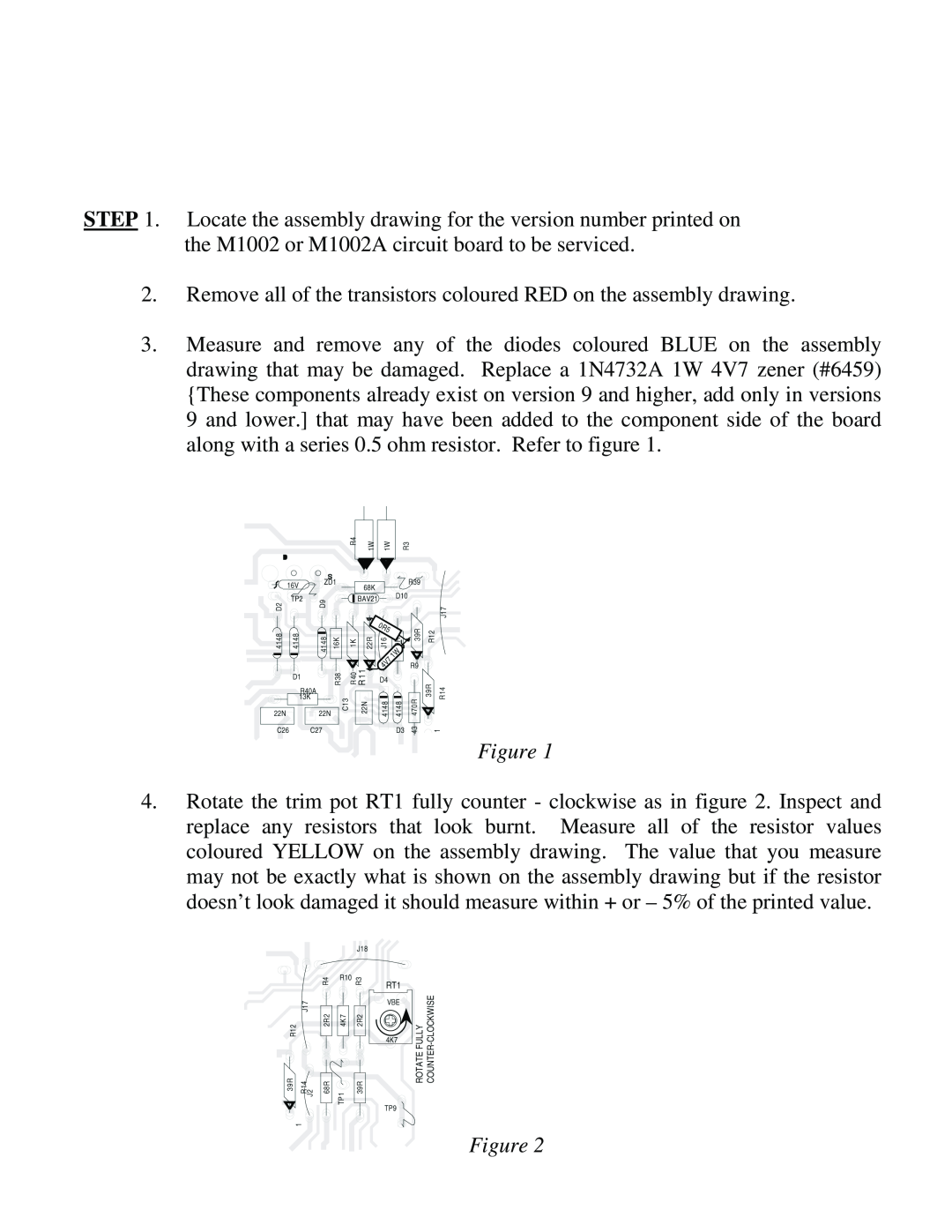
3.Measure and remove any of the diodes coloured BLUE on the assembly drawing that may be damaged. Replace a 1N4732A 1W 4V7 zener (#6459) {These components already exist on version 9 and higher, add only in versions 9 and lower.] that may have been added to the component side of the board along with a series 0.5 ohm resistor. Refer to figure 1.
Figure 1
4.Rotate the trim pot RT1 fully counter - clockwise as in figure 2. Inspect and replace any resistors that look burnt. Measure all of the resistor values coloured YELLOW on the assembly drawing. The value that you measure may not be exactly what is shown on the assembly drawing but if the resistor doesn’t look damaged it should measure within + or – 5% of the printed value.
Figure 2