EMS Circuit
The Energy Management System circuit only applies to North American line voltage products. A North American AC receptacle can provide 1850 watts before the wall breaker would trip, but how can a amplifier provide 2 x 1200 watts out when only 1850 watts is avaliable out of the AC receptacle? A sinewave source connected to the amplifier driving the amplfier to full power output will cause the circuit breaker on the amplifier to trip. Music driving the amplfier to clipping can be equal an average power output between 12 and 30 percent of the amplifier?s maximum capable power output. Under this condition less than 12 ampheres of current is drawn from the AC line. Some synthesized music may go beyond the 12 to 30 percent level and make the amplfier draw more than 12 amperes from the AC line. If this occurs the coil on board M1013A heats up to the point where through the heating of thermistor RV5, Q32 sinks current through R109. On board M1011A Q11 starts conducting through the connection to R109. Q11 heats thermistors RV2 and RV4 attenuating the audio signal going to each amplfier channel, thus decreasing the current drawn from the AC line to the point where less than 12 ampheres is being drawn.
Fan Circuit
Looking at the schematic to board M1013A, here is a quick explaination of the fan control circuit. There is a thermistor on each M1002A board. When the amplifier is first turned on, Q33 is saturated sinking the current source through ZD10. As either negative temperature coefficient thermistor begins to heat up, more current flows through D38 or D39 decreasing the conductor of Q33 until the increasing VCE of Q33 is enough to turn on Q34 and Q35. Further heating of the thermistor causes an increasing of Q33?s collector to emitter voltage. Q34 and Q35 are a common emitter stage with Q35
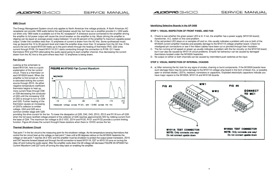
providing the drive current for the fan. To lower the dissipation of Q35, D42, D43, ZD12, ZD13 and R118 turn off Q35 when the full wave rectified voltage present of the collector of Q35 reaches approximently 50V by robbing current from the base of Q34. The maximum fan voltage is 20.5 VDC. ZD14 and R120, R121 and R122 provide a current limiting function. Figure #4 shows the current throught these resistors when there is 12VDC across the fan.
Thermal Shutdown Circuit
Test point 7 in the fan circuit is the measuring point for the shutdown voltage. As the temperature sensing thermistors that control the fan circuit heat up the voltage on test point 7 rises until at 85 degrees celcius on the M1002A heatsinks the voltage on test point 7 reaches 34.5 VDC and the amplifier must be shutdown to protect the output power transistors. ZD15 and D47 become forward biased and through the kill connection to board M1011A, Q37 on M1011A turns on turning the relay off and muting the audio signal. After the amplifier cools down the kill voltage will decrease FIGURE #4 AP3400 Fan Current Waveform until Q37 turns off turning the relay back on enabling the amplifier.
Identifying Defective Boards in the AP-3400
STEP 1: VISUAL INSPECTION OF FRONT PANEL AND FAN
A.Check to see whether the green power LED is lit. If not, the amplifier has a power supply (M1013A board), transformer, A.C. switch or line cord problem.
B.If the red protect LED stays on or samples off and on, this usually indicates a problem with one or both of the M1002A current amplifier modules and possibly damage to the M1011A voltage amplifier board. Check for misaligned pin connections or see if the ribbon cables have been cut or pinched through their insulation.
C.The fan running at full speed on power up usually indicates a problem with the fan circuitry on the M1013A board, but it can also be caused by M1011A circuit problems. Erractic fan behaviour can be caused by damaged thermistors located under the M1002A heatsinks.
D.No output on either or both channels can be caused by intermittent push switches at the input.
STEP 2: VISUAL INSPECTION OF INTERNAL CHASSIS
A.a) After removing the lid, look for any signs of smoke, charring or burnt components. If the M1002A boards have such damage there may be some damage to the M1011A voltage amp board in the form of blown ICs, or possibly open or shorted diodes, LED?s, resistors, transistors or capacitors. Exploded electrolytic capacitors indicate you have major repairs to the M1002A, M1011A and M1013A boards.
8 | 9 |