CHANNEL1 BAL LINE IN | MIC | CHANNEL 2 | BAL LINE IN | CD / LINE | LOW |
| HIGH | |||||
4 | 5 | 6 |
| 4 | 5 | 6 |
| 3 | 3 |
| 3 | 3 |
|
|
|
|
| ||||||||
3 |
| 7 |
| 3 |
| 7 |
| 6 |
| 6 | 6 |
|
2 |
| 8 |
| 2 |
| 8 |
| 9 |
| 9 | 9 |
|
1 |
| 9 |
| 1 |
| 9 |
| 12 |
| 12 | 12 |
|
0 |
| 10 |
| 0 |
| 10 |
| 15 | 15 |
| 15 | 15 |
KW | POWER | |
6 | BAL |
|
|
| |
9 |
|
|
12 |
|
|
EFX SEND | EFX RTN | PHONES |
230V
50Hz
0.5A
Yorkville |
120VAC
60Hz
1.0A
![]()
![]() KW
KW![]()
Introduction
The
Inputs
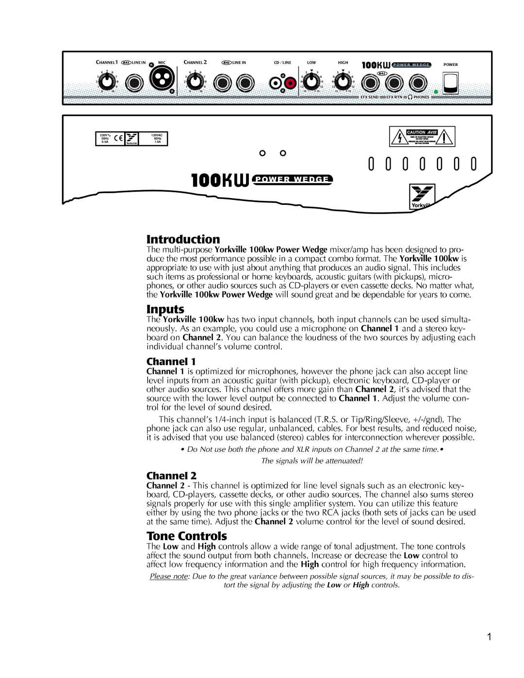
The Yorkville 100kw has two input channels, both input channels can be used simulta- neously. As an example, you could use a microphone on Channel 1 and a stereo key- board on Channel 2. You can balance the loudness of the two sources by adjusting each individual channel’s volume control.
Channel 1
Channel 1 is optimized for microphones, however the phone jack can also accept line level inputs from an acoustic guitar (with pickup), electronic keyboard,
This channel’s
•Do Not use both the phone and XLR inputs on Channel 2 at the same time.• The signals will be attenuated!
Channel 2
Channel 2 - This channel is optimized for line level signals such as an electronic key- board,
Tone Controls
The Low and High controls allow a wide range of tonal adjustment. The tone controls affect the sound output from both channels. Increase or decrease the Low control to affect low frequency information and the High control for high frequency information.
Please note: Due to the great variance between possible signal sources, it may be possible to dis-
tort the signal by adjusting the Low or High controls.
1
