APC Comprehensive Guide to A-Link Ports and Active Flow Controllers

Models: ACRC100 ACRC103

1 36
Download 36 pages 32.09 Kb
Page 31
Image 31

A-Link ports

Note: All input and output connections should be wired as Class 2 circuits.

Depending on the equipment configuration, additional control connections may be required for the A-Link remote communications through APC Network Management Card support or other equipment- monitoring software. A special RJ-45 terminator is provided and must be installed if both A-Link ports are not otherwise used, as shown.

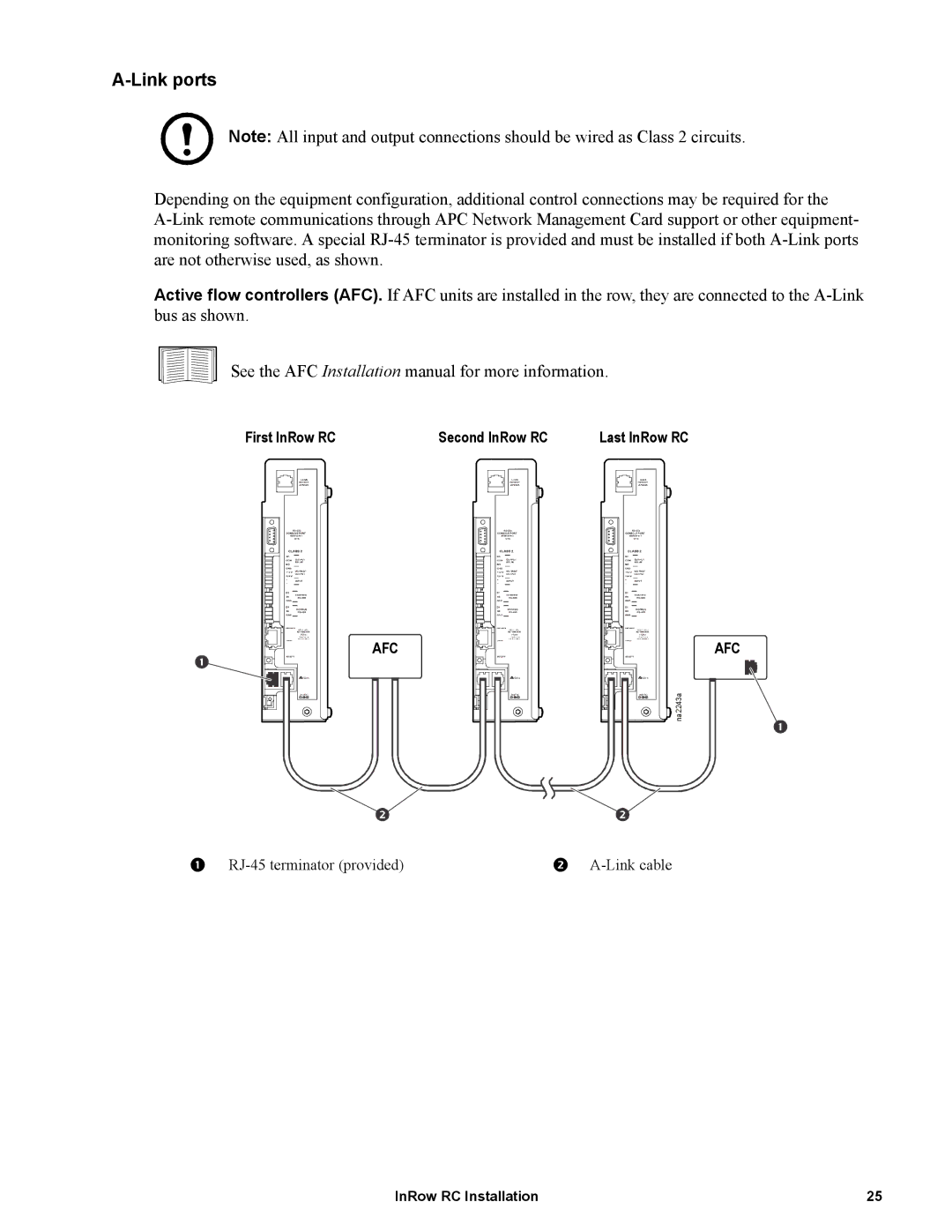
Active flow controllers (AFC). If AFC units are installed in the row, they are connected to the A-Link bus as shown.

See the AFC Installation manual for more information.

First InRow RC

Second InRow RC

Last InRow RC

AFC

AFC na2243a

1 RJ-45 terminator (provided)

2 A-Link cable

InRow RC Installation

25

Page 31
Image 31
APC ACRC100, ACRC103 manual Link ports