Piping Diagrams
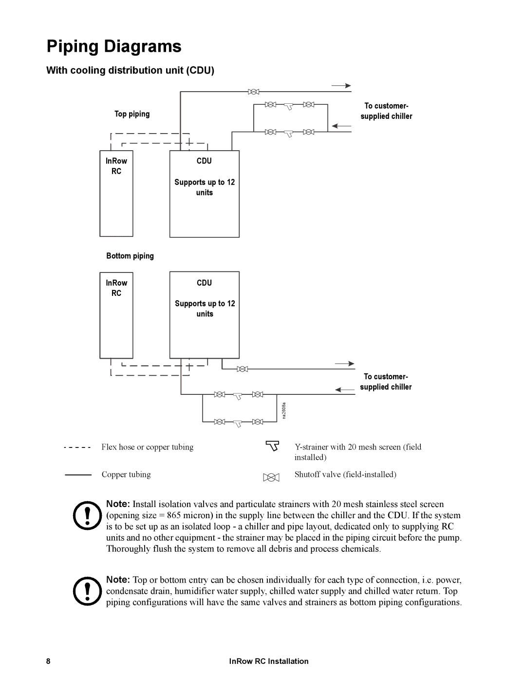
With cooling distribution unit (CDU)
Top piping | To customer- |
supplied chiller |
InRow | CDU |
RC | Supports up to 12 |
| |
| units |
Bottom piping |
|
InRow | CDU |
RC | Supports up to 12 |
| |
| units |
| To customer- |
| supplied chiller |
| na2608a |
Flex hose or copper tubing | |
| installed) |
Copper tubing | Shutoff valve |
Note: Install isolation valves and particulate strainers with 20 mesh stainless steel screen (opening size = 865 micron) in the supply line between the chiller and the CDU. If the system is to be set up as an isolated loop - a chiller and pipe layout, dedicated only to supplying RC units and no other equipment - the strainer may be placed in the piping circuit before the pump. Thoroughly flush the system to remove all debris and process chemicals.
Note: Top or bottom entry can be chosen individually for each type of connection, i.e. power, condensate drain, humidifier water supply, chilled water supply and chilled water return. Top piping configurations will have the same valves and strainers as bottom piping configurations.
8 | InRow RC Installation |