Power connections
Power cords may be routed through the top of the equipment (standard) or through the bottom (optional).
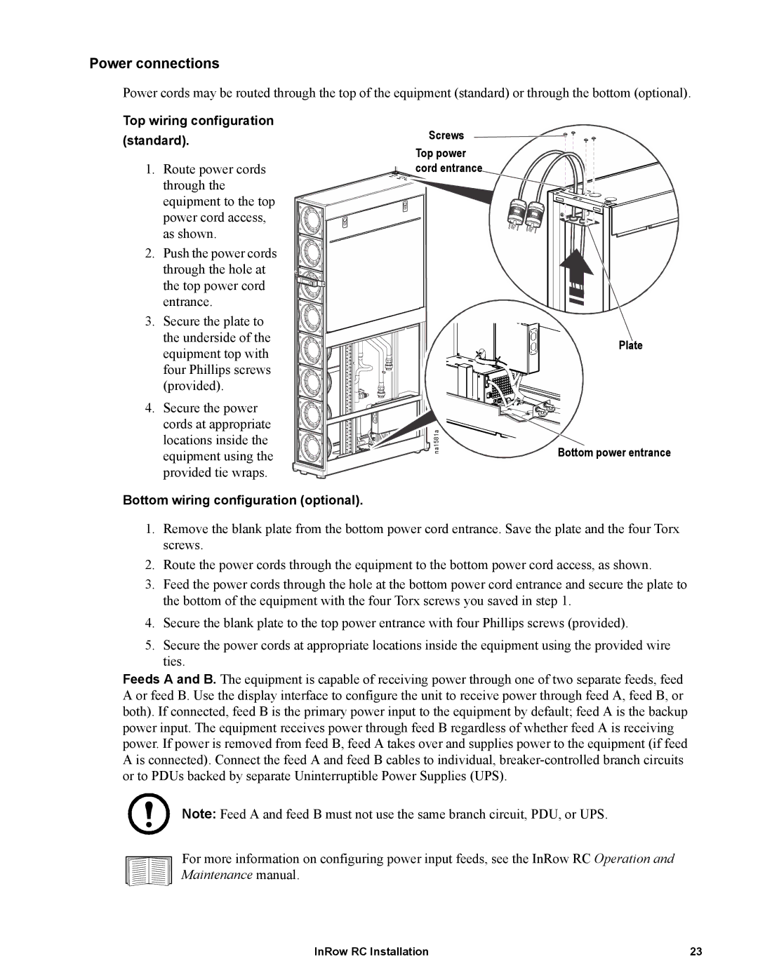
Top wiring configuration (standard).
1. Route power cords through the equipment to the top power cord access, as shown.
2. Push the power cords through the hole at the top power cord entrance.
3. Secure the plate to the underside of the equipment top with four Phillips screws (provided).
4. Secure the power cords at appropriate locations inside the equipment using the provided tie wraps.
Bottom wiring configuration (optional).
Screws
Top power cord entrance
na1581a
Plate
Bottom power entrance
1.Remove the blank plate from the bottom power cord entrance. Save the plate and the four Torx screws.
2.Route the power cords through the equipment to the bottom power cord access, as shown.
3.Feed the power cords through the hole at the bottom power cord entrance and secure the plate to the bottom of the equipment with the four Torx screws you saved in step 1.
4.Secure the blank plate to the top power entrance with four Phillips screws (provided).
5.Secure the power cords at appropriate locations inside the equipment using the provided wire ties.
Feeds A and B. The equipment is capable of receiving power through one of two separate feeds, feed A or feed B. Use the display interface to configure the unit to receive power through feed A, feed B, or both). If connected, feed B is the primary power input to the equipment by default; feed A is the backup power input. The equipment receives power through feed B regardless of whether feed A is receiving power. If power is removed from feed B, feed A takes over and supplies power to the equipment (if feed A is connected). Connect the feed A and feed B cables to individual,
Note: Feed A and feed B must not use the same branch circuit, PDU, or UPS.
For more information on configuring power input feeds, see the InRow RC Operation and Maintenance manual.
InRow RC Installation | 23 |