YS1083 specifications
Yorkville Sound has established itself as a prominent name in the audio equipment industry, and the YS1083 is a testament to their dedication to quality and performance. This powered speaker, designed primarily for live sound applications, is a versatile solution for both professional and amateur audio enthusiasts.One of the standout features of the YS1083 is its impressive power output. Equipped with an 800-watt peak power amplifier, it ensures that the sound is not only loud but also clear and crisp. This amplifier is paired with high-quality transducers that optimize sound reproduction across various frequencies, ensuring that every note and vocal nuance is delivered with precision.
The speaker boasts an 8-inch neodymium woofer which provides deep, rich bass, while the 1-inch compression driver handles the high frequencies, resulting in a full-spectrum sound that is ideal for dynamic performances. The YS1083's frequency response range is designed to cater to a broad array of audio content, making it suitable for everything from music performances to spoken-word events.
Portability is another key feature of the YS1083. Weighing in at just over 30 pounds, it is designed for easy transport without sacrificing durability. The cabinet is constructed from tough, lightweight materials, and its rugged design ensures that it can withstand the rigors of regular transport and use.
Additionally, the YS1083 includes convenient built-in EQ controls, allowing users to tailor the sound to their specific needs in real-time. This gives sound engineers and performers the flexibility to adjust settings on the fly, enhancing the overall audio experience.
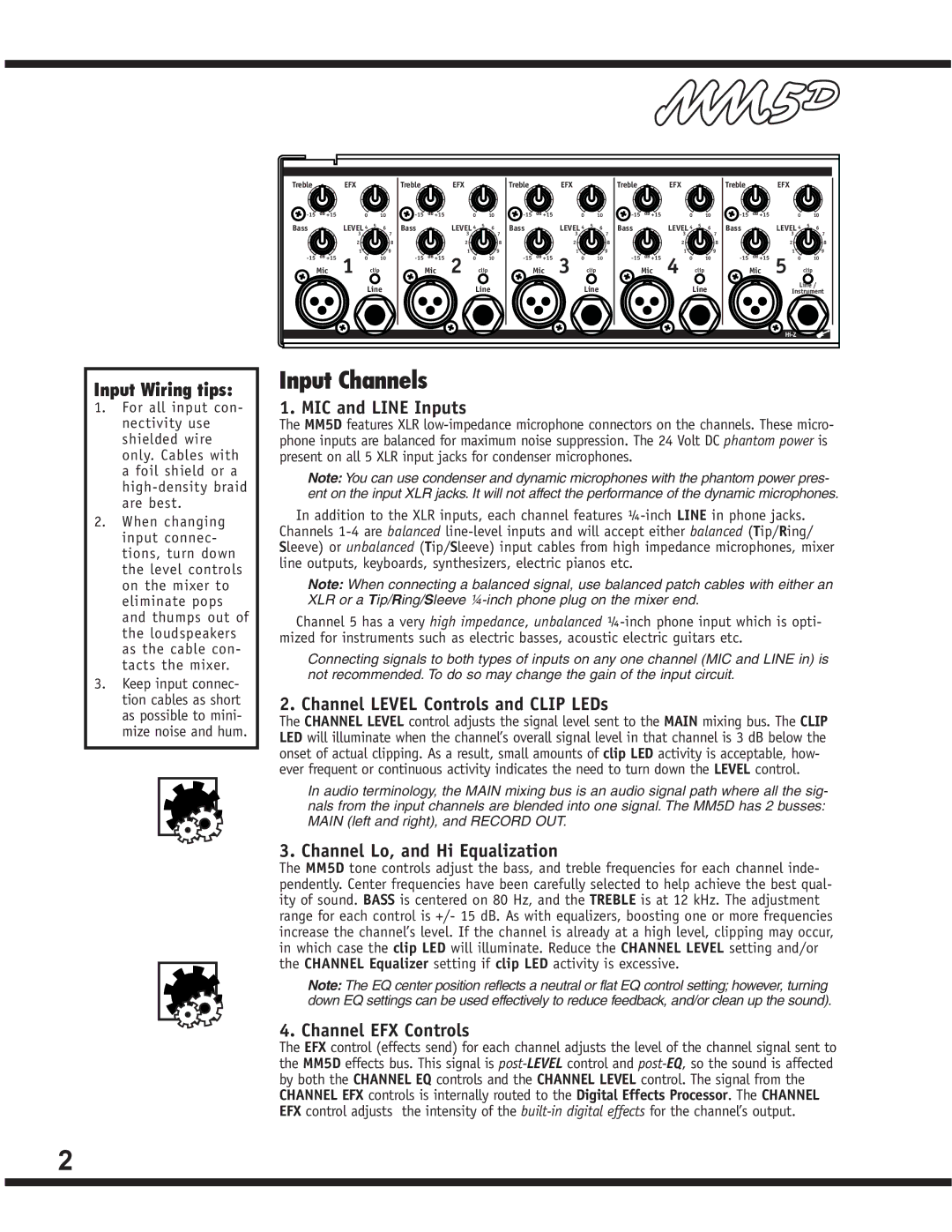
Another noteworthy characteristic is the YS1083's versatility in terms of input options. It comes equipped with multiple input channels, including XLR and 1/4-inch connections, enabling it to be used with a variety of microphones and instruments. The integrated mixer allows for seamless transitions between different audio sources, making it perfect for multi-performer setups.
Overall, the Yorkville Sound YS1083 is a robust and flexible option for anyone needing a reliable powered speaker. Its combination of power, portability, and sound quality makes it an excellent choice for gigs, events, and installations alike. Whether in a small venue or a larger auditorium, the YS1083 delivers the auditory performance that Yorkville Sound is known for, making it a standout in the world of professional audio equipment.

