ELECTRICAL CONNECTIONS
WARNING: THIS APPLIANCE MUST BE EARTHED.
The manufacturer declines any liability should this safety measure not be observed.
Ensure that the electric circuit is capable of carrying the load of the appliance.
Switch OFF the electricity supplies at the mains.
A double pole cooker control switch with a suitable electrical rating should be used to control the electrical supply to the hob.
The control switch should be easily accessible to the user on completion of the installation.
The control switch must not break the yellow/green earth wire at any point.
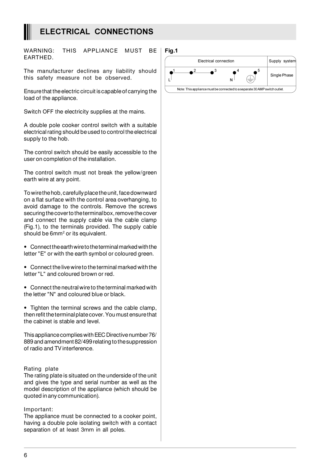
To wire the hob, carefully place the unit, face downward on a flat surface with the control area overhanging, to avoid damage to the controls. Remove the screws securing the cover to the terminal box, remove the cover and connect the supply cable via the cable clamp (Fig.1), to the terminals provided. The supply cable should be 6mm2 or its equivalent.
•Connect the earth wire to the terminal marked with the letter "E" or with the earth symbol or coloured green.
•Connect the live wire to the terminal marked with the letter "L" and coloured brown or red.
•Connect the neutral wire to the terminal marked with the letter "N" and coloured blue or black.
•Tighten the terminal screws and the cable clamp, then refit the terminal plate cover. You must ensure that the cabinet is stable and level.
This appliance complies with EEC Directive number 76/ 889 and amendment 82/499 relating to the suppression of radio and TV interference.
Rating plate
The rating plate is situated on the underside of the unit and gives the type and serial number as well as the model description of the appliance (which should be quoted in any communication).
Important:
The appliance must be connected to a cooker point,
having a double pole isolating switch with a contact separation of at least 3mm in all poles.
Fig.1
|
| Electrical connection |
| Supply system |
1 | 2 | 3 | 4 | 5 |
|
|
|
| Single Phase |
L |
| N |
|
|
Note: This appliance must be connected to a separate 30 AMP switch outlet.
6