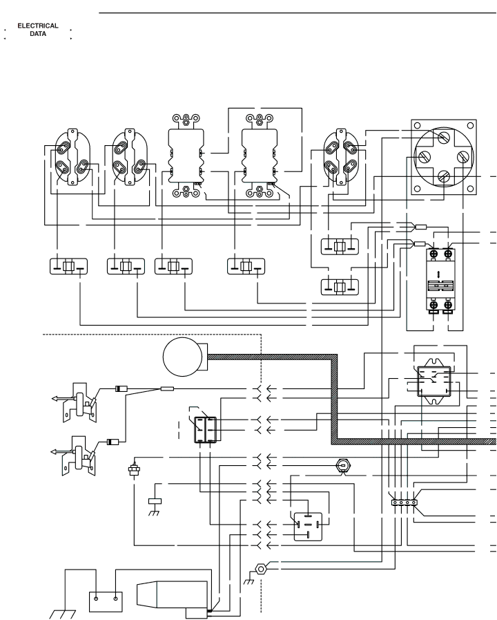
Section 8 — Electrical Data
Wiring Diagram, Portable Generator – Drawing No. 0G0731
|
|
|
|
|
|
|
|
|
|
|
| 22 |
|
|
|
|
|
|
|
|
|
|
|
|
|
| 120V/20A |
|
|
|
| 120V/20A |
| 120/240V | |||
| 120V/30A |
| 120V/30A |
|
|
|
|
|
|
|
| 30A TWISTLOK | ||||||
|
|
|
|
|
| DUPLEX |
|
|
|
| GFCI |
| ||||||
|
|
|
|
|
|
|
|
|
|
|
|
|
| |||||
| TWISTLOK |
| TWISTLOK |
|
|
|
|
| 22 |
|
|
|
| 22 |
|
|
| |
|
|
|
|
|
|
|
|
|
|
|
|
|
|
|
|
| ||
WHITE |
| WHITE |
|
|
|
|
|
|
|
|
|
|
|
|
| X |
| G |
|
|
|
|
|
|
| WHITE |
|
|
|
|
| WHITE |
|
|
| ||
22 | G | G |
|
| 1 | HOT | 2 | 22 | 1 | HOT | LOAD | 2 |
| WHITE |
|
| ||
| 0 |
|
| 0 |
| HOT | WHITE |
|
|
| HOT |
| WHITE |
| 11B |
|
|
|
|
|
|
|
|
|
|
|
|
|
|
|
| ||||||
22 | 22 |
|
|
| 3 |
|
| 4 | 22 | 3 |
| LINE |
| 4 22 |
|
|
| Y |
|
|
|
|
|
|
|
|
|
|
| ||||||||
|
|
|
|
|
|
|
|
|
|
|
|
| ||||||
|
|
|
|
|
|
|
| 5 |
|
|
|
|
| 5 |
|
|
|
|
44D | 0 | 11D | 0 | 11C |
|
|
| 0 | 44C |
|
|
| 0 | 22 | 22 |
| ||
|
|
|
|
|
|
|
|
|
|
|
|
|
| |||||
|
|
|
|
|
|
|
|
|
|
| 0 |
| 0 | 0 |
|
|
| |
|
|
|
|
|
|
|
|
|
|
|
|
|
|
|
| |||
|
|
|
|
|
|
|
|
|
|
| 22 |
|
| 22 |
|
|
| |
| 22 |
|
| 0 |
|
|
|
|
|
| 0 |
|
|
|
|
|
| |
|
|
|
|
|
|
|
|
|
| 22 |
|
|
|
| 30A |
| ||
|
|
|
|
|
|
|
|
|
|
|
|
|
|
| 11B | 44B | 44 | |
|
|
|
|
|
|
|
|
|
|
|
|
|
|
| C.B. | |||
44D 30A |
| 11D 30A |
| 11C 20A |
|
|
| 44C 20A |
|
|
|
|
|
|
| |||
C.B. | C.B. |
|
| C.B. |
|
|
| C.B. |
|
|
|
|
|
|
| |||
|
|
|
|
|
|
|
|
|
|
|
|
|
|
|
| 11B | 30A | 11 |
| 44 | 11 |
|
|
| 11 |
|
|
|
|
| 44 |
|
|
| C.B. | ||
|
|
|
|
|
|
|
|
|
|
|
|
|
|
| ||||
|
|
|
|
|
|
|
|
|
|
|
|
|
|
| 44 |
|
|
|
|
|
|
|
|
|
|
|
|
|
|
|
|
|
| 11 |
|
|
|
|
|
|
|
|
|
|
|
|
|
|
|
|
|
| 11 |
|
|
|
|
|
|
|
|
|
|
|
|
|
|
|
|
|
| 44 |
|
|
|
ENGINE WIRING |
|
|
|
|
|
|
|
|
|
|
|
|
|
|
|
| ||
|
|
|
|
| GOVERNOR |
|
|
|
|
|
|
|
|
|
|
| ||
|
|
|
|
| ACTUATOR |
|
|
|
|
|
|
|
|
|
|
| ||
|
|
|
| IC |
|
|
|
| 18 | 1 |
| 18 |
|
|
|
| ||
|
|
|
|
|
|
|
|
|
|
|
|
|
|
| ||||
SP1 |
| D |
|
|
|
|
|
|
| 15 | 2 |
| 15 |
|
|
|
| |
|
|
|
|
|
|
|
|
|
|
|
|
|
| |||||
| IM1 |
|
|
|
|
| 0 | 0 |
|
|
|
|
|
|
|
|
|
|
|
|
|
|
|
|
|
|
|
|
|
|
|
|
|
|
| ||
|
|
|
| (START) |
|
|
| 0 | 3 |
| 0 |
|
|
|
| |||
|
|
|
|
|
|
|
|
|
|
|
|
| ||||||
|
|
|
|
| RUN |
|
|
| 167 | 4 |
| 167 |
|
|
|
| ||
|
|
|
|
| STOP |
|
|
|
|
|
|
|
|
|
|
|
| |
SP2 |
| D |
|
|
|
|
| 17 | 15 |
|
|
|
|
|
|
|
|
|
|
|
| 86 |
|
|
|
| 86 | 5 |
| 86 |
|
|
|
| |||
|
|
|
|
|
|
|
|
|
|
|
|
| ||||||
| IM2 |
|
|
|
|
|
|
|
| 13 | 6 |
| 13 |
|
|
| F1 | |
| LOP |
|
|
|
|
|
|
|
|
|
|
|
| 15 |
|
|
| |
|
|
|
|
|
|
|
|
|
|
|
|
|
|
|
|
|
| |
|
| 0 |
| 14 |
|
|
|
|
| 14 | 7 |
| 14 |
|
|
|
| |
|
|
|
|
|
|
|
|
|
|
|
|
|
| |||||
|
|
|
|
|
|
|
|
|
| 17 | 8 |
| 17 |
|
|
|
| |
|
|
| FSS |
|
|
|
|
| 16 | 9 |
| 16 |
|
|
|
| ||
|
|
|
|
|
|
|
|
|
|
|
|
|
| 15 |
|
|
|
|
|
|
|
|
|
|
|
|
|
|
|
|
|
|
| 87 | 17 |
| 14 |
|
|
|
|
|
|
|
|
|
|
|
|
|
|
|
|
|
| |
|
|
|
|
|
|
|
|
|
| 15 | 10 |
| 15 | 86 |
|
|
| |
|
|
|
|
|
|
|
|
|
|
| 87a |
|
|
| ||||
|
|
|
|
|
|
|
|
|
|
|
|
|
|
| 85 |
|
|
|
|
|
|
|
|
|
|
|
|
| 13 | 11 |
| 13 | 30 | SCR |
|
| |
|
|
|
|
|
|
|
|
|
|
|
|
|
|
|
|
| ||
|
|
|
|
| 0 |
|
|
| 0 | 12 |
| 0 |
|
|
|
| ||
|
|
|
|
|
|
|
|
|
|
|
| PIN # |
|
|
|
|
| |
|
|
|
|
|
|
|
|
|
|
|
|
|
| 0 |
|
|
|
|
| BLACK |
|
| RED |
|
|
|
|
|
|
|
|
| 0 |
|
|
|
|
|
|
|
|
|
|
|
|
|
|
|
|
|
|
|
|
| ||
|
|
|
|
|
|
|
|
|
| 13 |
|
|
|
|
|
|
|
|
| - | + |
|
|
| SM |
|
| 13 | 16 |
|
|
|
|
|
|
|
|
|
|
|
|
|
|
|
|
|
|
|
|
|
|
|
|
| ||
| 12V |
|
|
|
|
|
|
|
|
|
|
|
|
|
|
|
| |
BATTERY
SC
120/240V (50A/60A) OUTLET
|
| 0 |
|
|
0 |
| 0 |
|
|
|
|
| GREEN | |
0 |
|
| X | Y |
|
|
|
| |
|
|
| WHITE | |
|
|
|
| 22 |
22 |
|
|
|
|
|
|
| 22 |
|
|
|
| 11A | 44A |
|
| 44 |
|
|
|
| 44 |
|
|
|
| 44 |
| 11 |
| 0 |
| 11 | 44 |
|
|
| 44 | |
|
|
|
| |
44 |
| 11 |
|
|
44 |
| 11 | 50A/ |
|
| 60A |
| ||
|
|
|
| |
11 C.B.
| ON |
11A | OFF |
|
11A 44A
14
18
1418
1 2 4
515B
|
|
| 15 |
|
| 6 | 8 | 0 |
|
|
|
| 15 | 9 | 10 | 12 | |
|
|
|
|
| SSR |
| 229 | |
|
|
|
|
| 13 | 14 | ||
|
|
|
|
|
|
|
| 14 |
|
|
|
|
|
|
|
| 0 |
|
|
|
|
|
|
|
| 167 |
|
|
|
|
|
|
|
| 0 |
0 | 0 | 0 | 0 |
| 15 |
|
| 86 |
|
|
|
|
|
|
|
| 0 |
|
|
|
|
|
|
|
| 15 |
|
|
|
|
|
|
|
| 0 |
15 |
|
|
|
|
|
|
| 15 |
| 0 | 0 | 0 | 0 | 0 |
|
| 0 |
|
|
|
|
| GND |
|
|
|
0 |
| 0 | 0 | 0 55 |
|
| 55A | |
|
|
|
|
|
|
|
| 55 |
0
14
28