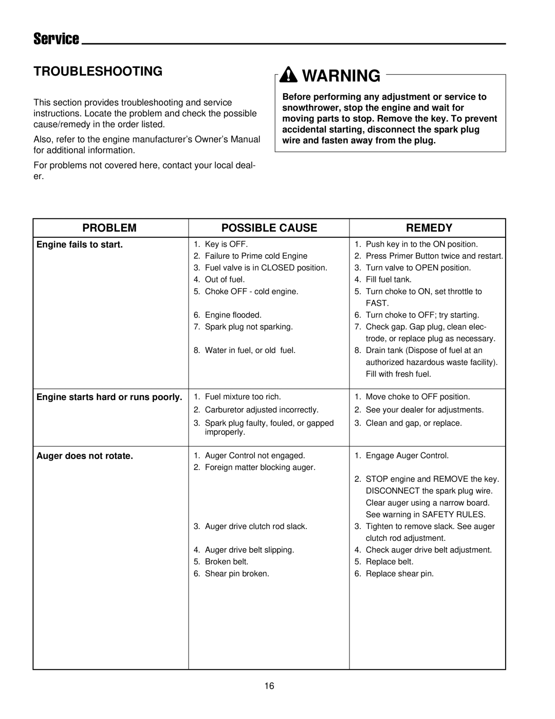
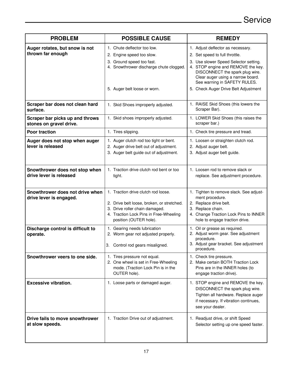
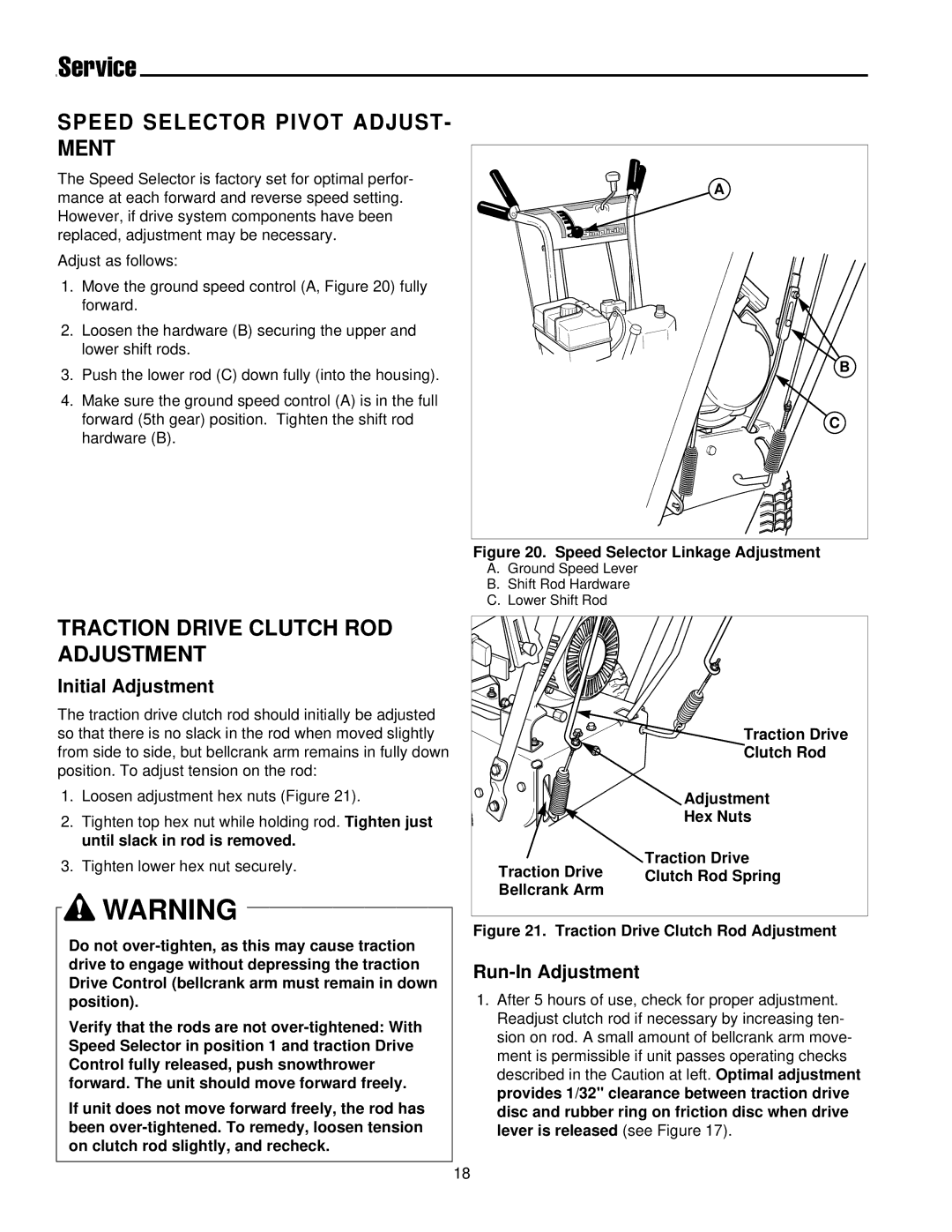
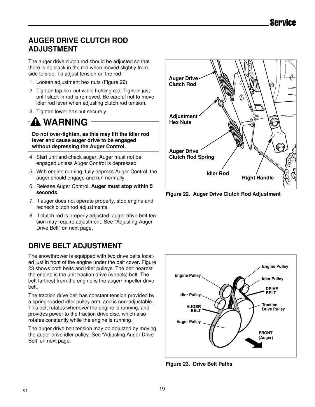
Simplicity 1693647 555M manual Discharge Chute Worm Assembly Adjustment, Checking Tire Pressure

Page 28

Service

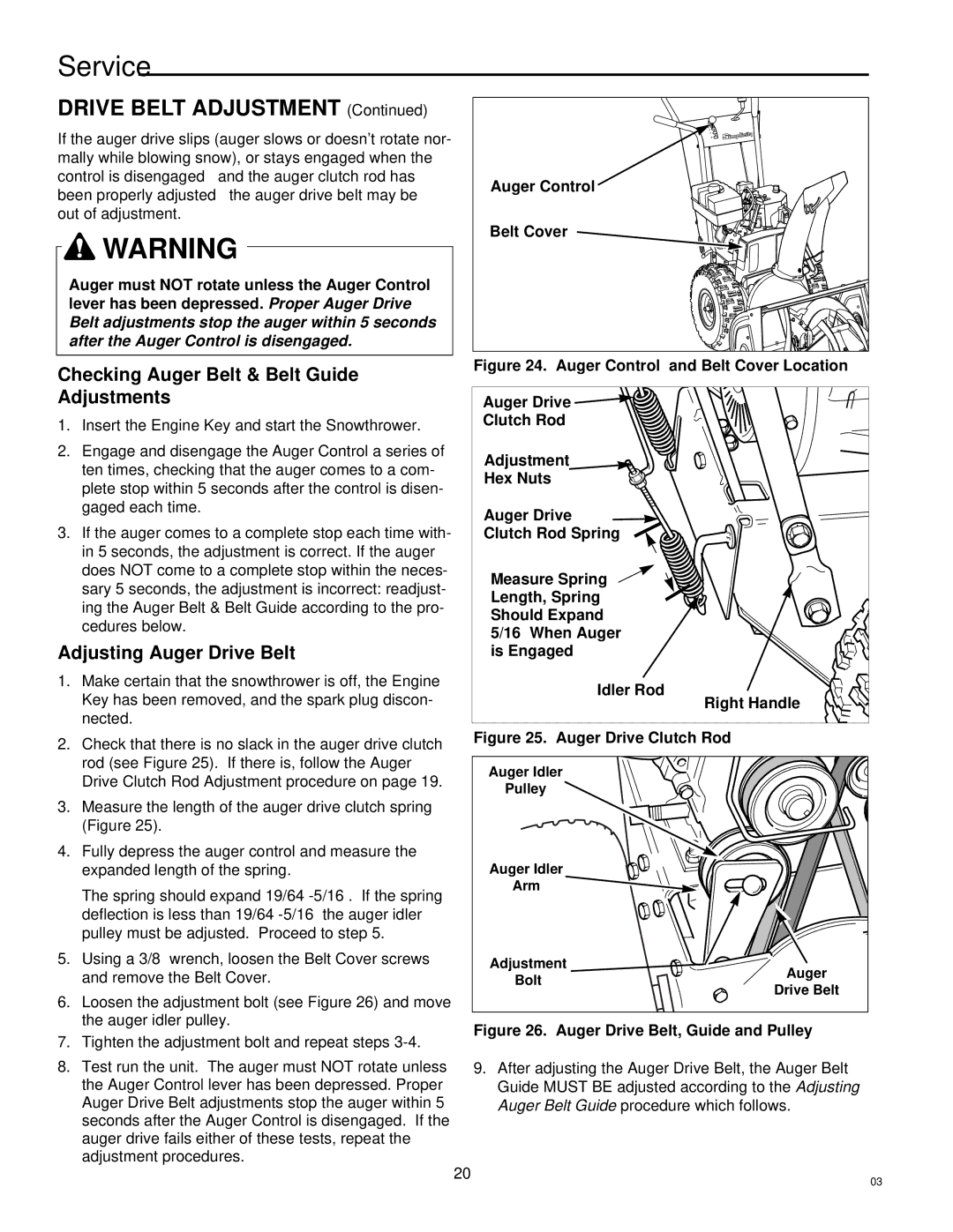
DISCHARGE CHUTE WORM

ASSEMBLY ADJUSTMENT

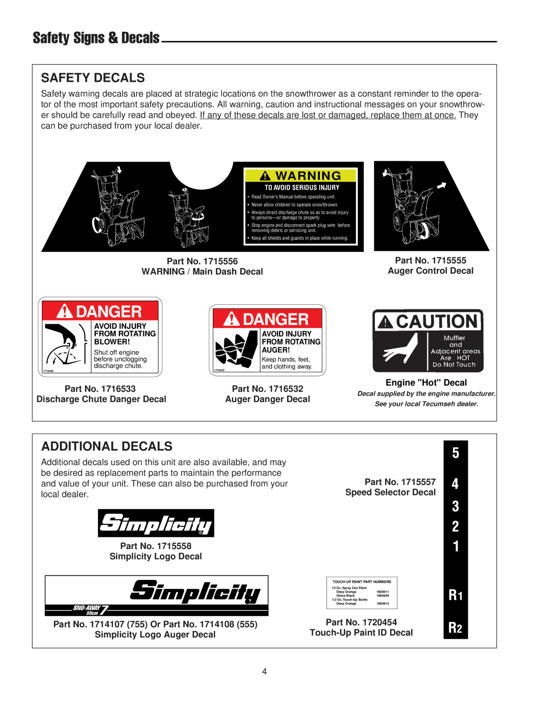
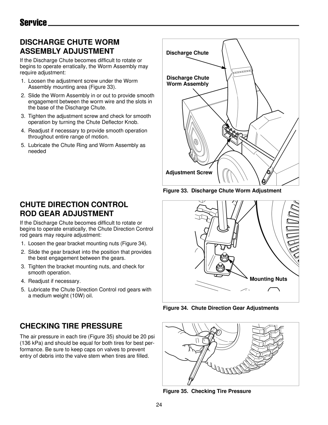
If the Discharge Chute becomes difficult to rotate or begins to operate erratically, the Worm Assembly may require adjustment:

1.Loosen the adjustment screw under the Worm Assembly mounting area (Figure 33).

2.Slide the Worm Assembly in or out to provide smooth engagement between the worm wire and the slots in the base of the Discharge Chute.

3.Tighten the adjustment screw and check for smooth operation by turning the Chute Deflector Knob.

4.Readjust if necessary to provide smooth operation throughout entire range of motion.

5.Lubricate the Chute Ring and Worm Assembly as needed

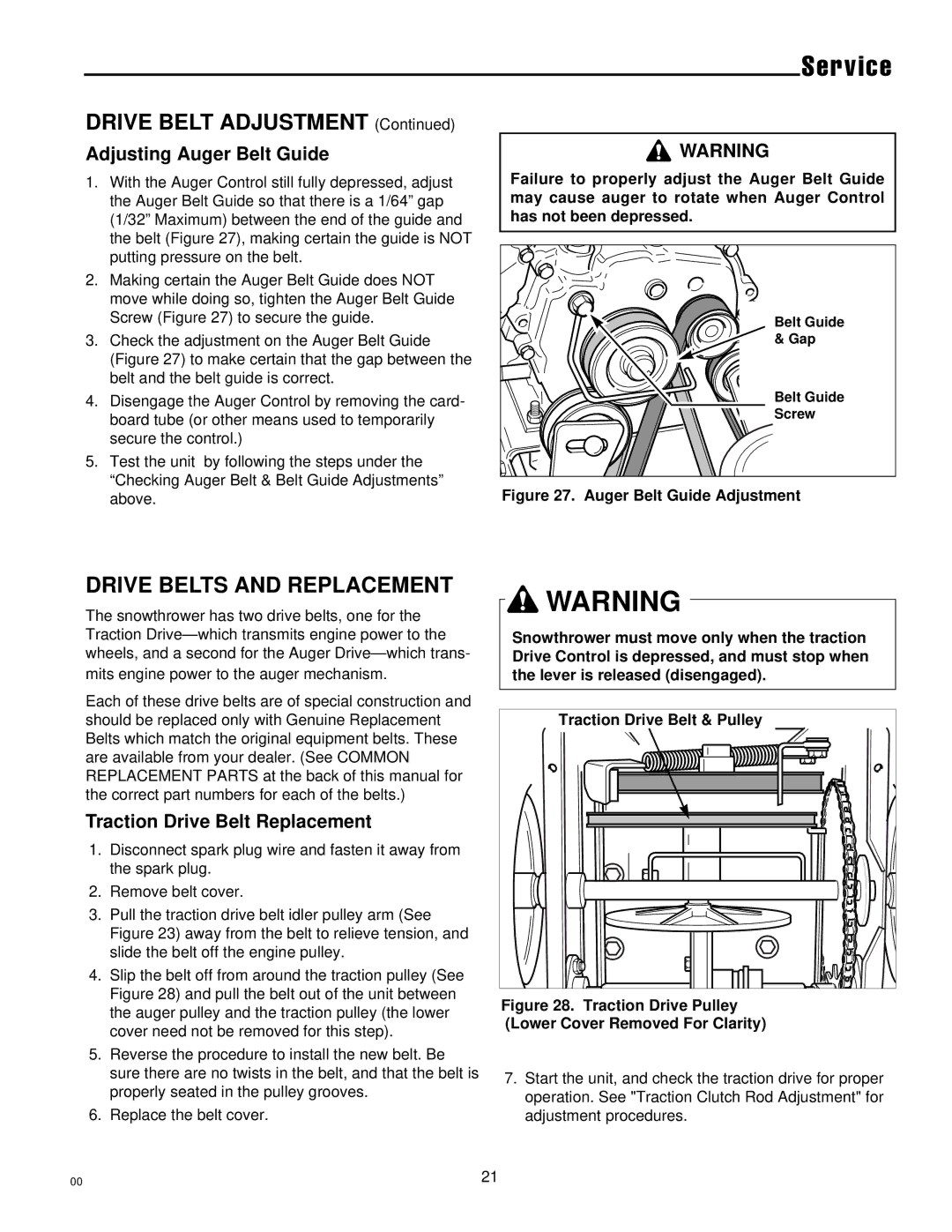
CHUTE DIRECTION CONTROL ROD GEAR ADJUSTMENT

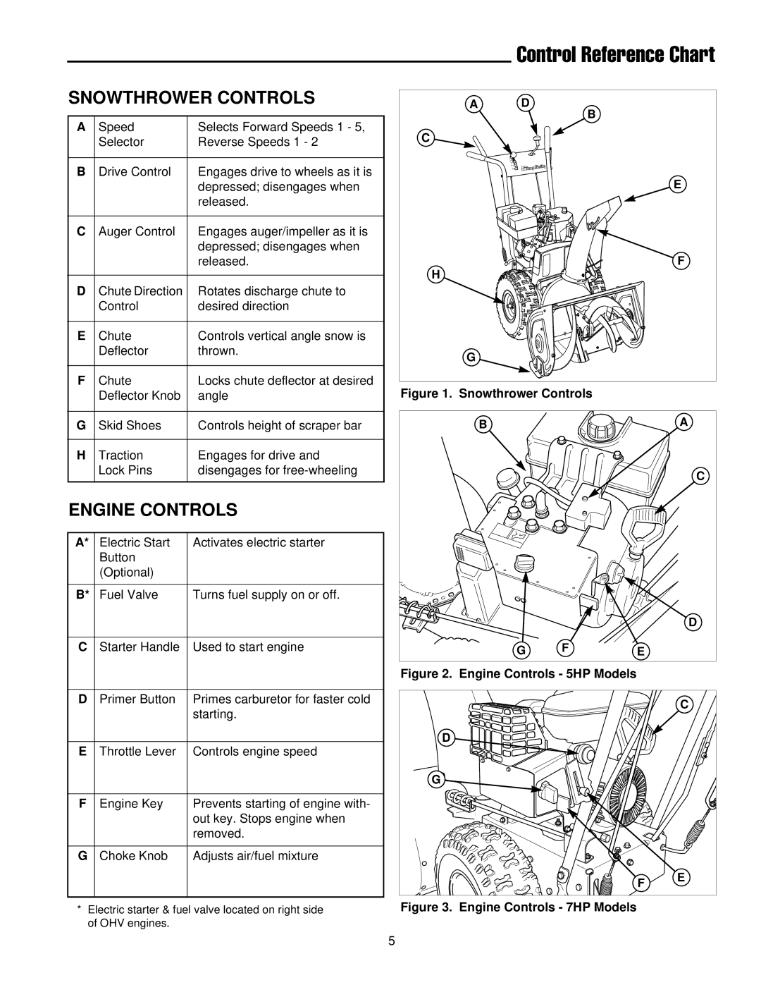
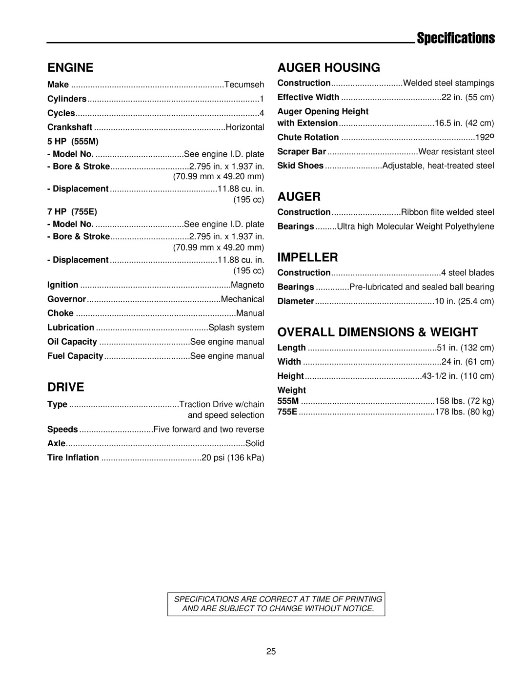
If the Discharge Chute becomes difficult to rotate or begins to operate erratically, the Chute Direction Control rod gears may require adjustment:

1.Loosen the gear bracket mounting nuts (Figure 34).

2.Slide the gear bracket into the position that provides the best engagement between the gears.

3.Tighten the bracket mounting nuts, and check for smooth operation.

4.Readjust if necessary.

5.Lubricate the Chute Direction Control rod gears with a medium weight (10W) oil.

Discharge Chute

Discharge Chute

Worm Assembly

Adjustment Screw

Figure 33. Discharge Chute Worm Adjustment

Mounting Nuts

Figure 34. Chute Direction Gear Adjustments

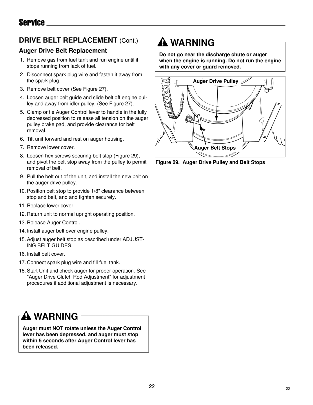
CHECKING TIRE PRESSURE

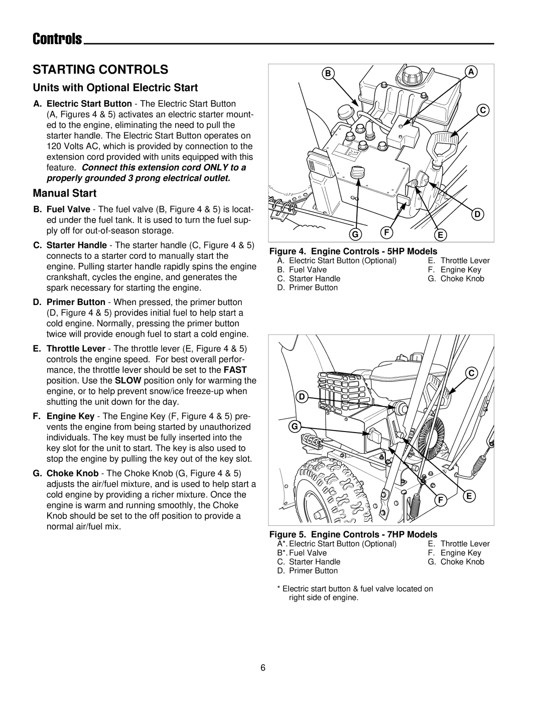
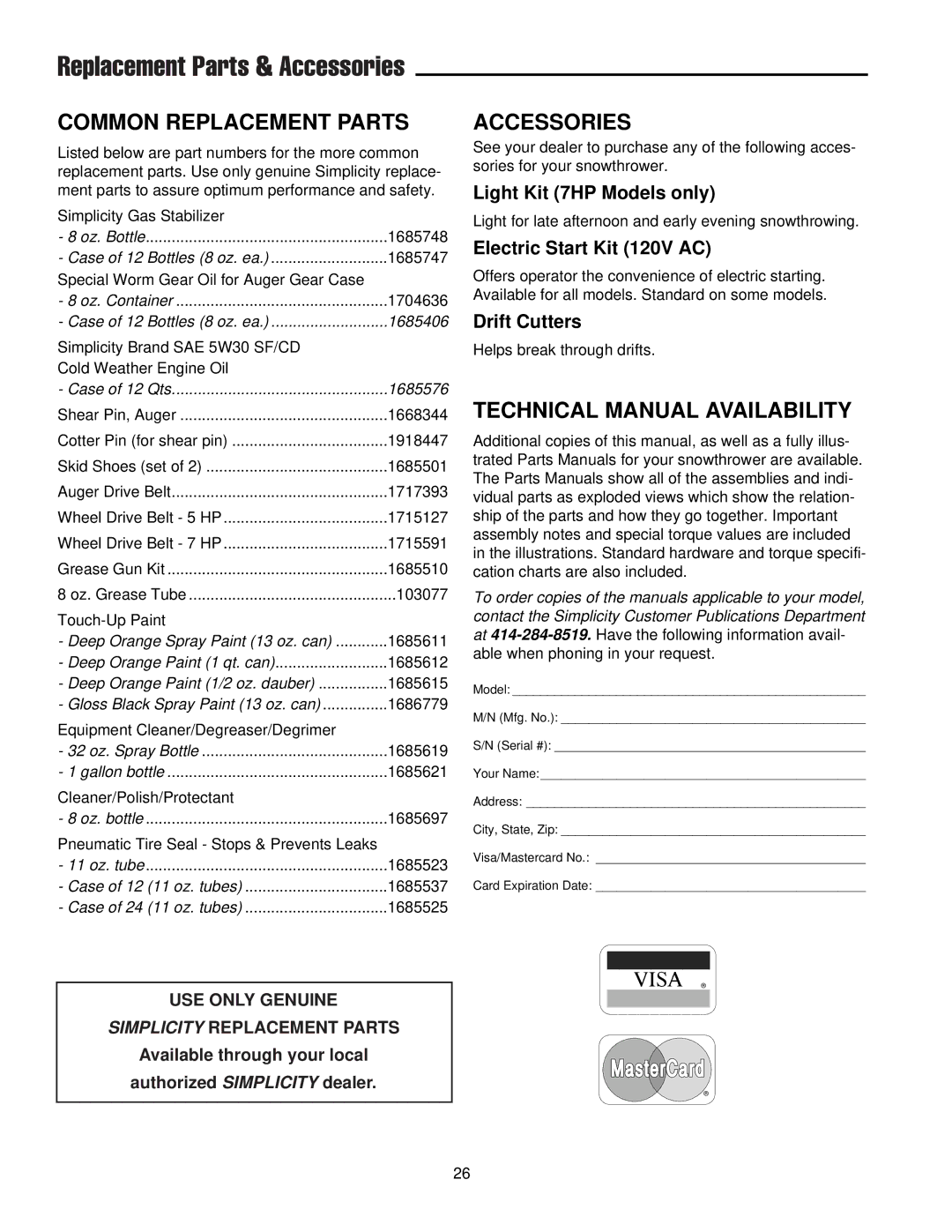
The air pressure in each tire (Figure 35) should be 20 psi (136 kPa) and should be equal for both tires for best per- formance. Be sure to keep caps on valves to prevent entry of debris into the valve stem when tires are filled.

Figure 35. Checking Tire Pressure

24
Image 28
Contents How to use this file...Operators Manuals Simplicity Technical Publications Department at 414This page Intentionally Blank OPERATOR’S Manual ModelsPage Table Of Contents General Safety RulesPreparation Maintenance & Storage OperationSafety Decals Safety Signs & DecalsAdditional Decals Snowthrower Controls Control Reference ChartEngine Controls Controls Starting ControlsUnits with Optional Electric Start Manual StartGround Speed Controls Auger ControlDeflector Controls Scraper Height ControlOperation Checks Before Each START-UPStarting the Engine OperationOperating the Snowthrower Ground Speed SelectorEngine Speed ThrottleDeflector Scraper BAR & Skid ShoesFREE-WHEELING Traction Drive Lock After Each USEKlik-Pin Outer Hole Klik-Pin Inner HoleNormal Care OFF-SEASON StorageStarting After Storage Check Auger Gear Case LubricationRegular Maintenance LubricationDriv e Disc Friction DiscMaintenance Records Service TroubleshootingEngine fails to start Engine starts hard or runs poorlyScraper bar does not clean hard Auger does not stop when augerAuger rotates, but snow is not Thrown far enoughSpeed Selector Pivot ADJUST- Ment Traction Drive Clutch ROD AdjustmentInitial Adjustment Run-In AdjustmentDrive Belt Adjustment Auger Drive Clutch ROD AdjustmentRelease Auger Control. Auger must stop within 5 seconds Checking Auger Belt & Belt Guide Adjustments Adjusting Auger Drive BeltAuger Control Belt CoverDrive Belts and Replacement Adjusting Auger Belt GuideTraction Drive Belt Replacement Lower Cover Removed For ClarityDrive Belt Replacement Auger Drive Belt ReplacementRoller Chain Replacement Shear PIN ReplacementPins Keeper linkDischarge Chute Worm Assembly Adjustment Checking Tire PressureAuger Housing Overall Dimensions & WeightEngine DriveAccessories Common Replacement PartsTechnical Manual Availability