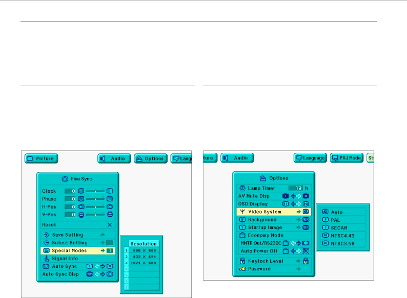
Philips PXG20 Picture control, Picture Control, Data Mode Input Signal, Video Mode Input Signal

Page 19

8. OPERATION

Picture control


PICTURE CONTROL

The projector’s picture is set to standard specifications at the factory. However, you can adjust the image to suit your own preferences by using the Data or Video ADJUST feature.

The projector will store the last used settings for every source. So when you switch from one source to another, the settings of the source switched from will be stored and the settings of the source switched to will be recalled.

When the projector is switched off and on again the settings for the selected source will be recalled again.

Three memory modes allow you to adjust and save up to three sets of settings (see ‘Personal Preferences’).

DATA MODE INPUT SIGNAL

Data mode input selection

Ordinarily, the type of input signal is detected and the correct resolution mode is automatically selected. However, for some signals, ‘Special Modes’ on the ‘Fine Sync’ menu screen may need to be changed to match the computer display mode.

1.Press Menu.

2.Press 1 / 2 to select ‘Fine Sync’.

3.Press 3 / 4 to select ‘Special Modes’.

VIDEO MODE INPUT SIGNAL

Video mode system selection

The video input system mode is preset to ‘Auto’; however, it can be changed to a specific system mode, if the selected system mode is not compatible with the connected audiovisual equipment.

1.Press Menu.

2.Press 1 / 2 to select ‘Options’.

3.Press 3 / 4 to select ‘Video System’.

4.Press OK to move into the Special Modes.

5.Press 4 to select the optimal resolution mode.

6.Press OK to save the setting.

7.To exit from the GUI, press Menu.

Notes:

Avoid displaying computer patterns which repeat every other line (horizontal stripes). (Flickering may occur, making the image hard to see.)

When inputting DTV 480P signals, select ‘480P’ in step 4 above.

4.Press OK to move into the Video System mode.

5.Press 4 to select the desired video system mode.

6.Press OK to save the setting.

7.To exit from the GUI, press Menu.

17

Image 19
Contents User guide Important Note for Users in the U.S.A Reference Important SafeguardsIntroduction FCC Warning Things YOU should KnowComputer RGB / Component inputs Advanced Compatibility with HIGH-END Workstations and PC’s Projector FeaturesLamp Monitor Function Temperature Monitor FunctionOn projector fig Functional OverviewSee illustrations on ControlsRemote Control Connections Positioning the Projector and Screen SET UPPower Supply Using the adjustment feetInserting the Batteries in the Remote Control Lens AdjustmentMoving the Projector Video/computer cables and adapter InstallationVIDEO/COMPUTER Cables and Adapter Connecting to a Computer Connecting to a computerGeneral Case your VCR, Laser Disc player, video camera or TV is Connecting to video equipmentConnecting to Video Equipment Equipped with a Scart connectorConnecting to Audio Equipment Connecting to audio equipment/remote control mouse receiverConnecting the Remote Control Mouse Receiver Preparation Using the Remote ControlOperation PreparationGraphical User Interface Data Mode Menu ControlVideo Mode Menu Control Graphical User InterfacePicture Control Data Mode Input SignalVideo Mode Input Signal Picture controlAuto Sync Adjustment Data Mode DisplayData display Fine Sync adjustments Description of Adjustment ItemsAuto Sync Display Function Data Mode / Video Mode DisplayPicture adjustments Color Temperature adjustmentsAudio Control Interlaced modeProgressive mode Picture control/Audio controlPersonal Preferences Saving/changing the adjustment settingSelecting a saved setting Personal preferencesDigital Freeze Function D-FREEZE Other SettingsCeiling-mount Setup REVERSE/INVERT Image FunctionEffect Modes Data Mode Picture display mode Format on projector keyboard onlyVideo Mode Setting the Password Selecting the Keylock Level Changing the PasswordChecking the Input Signal Setting a Background ImageStatus Function Selecting a Startup ImageMenu Tree Data Mode Video Mode Main MenuLamp/Maintenance Indicators Connecting RS-232C port/MaintenanceCleaning and replacing the bottom air filter Cleaning the side air filter not removableReplacing the lamp MaintenanceMaintenance Indicator Condition Problem Possible Solution Lamp LCA 3112 8670 931Kensington Lock Resetting the lamp timerTroubleshooting