Cisco Systems ME 2400 manual Connector and Cable Specifications, Connector Specifications

Page 59

A P P E N D I X B

Connector and Cable Specifications

This appendix describes the Cisco ME switch ports and the cables and adapters that you use to connect the switch to other devices.

Connector Specifications

These sections describe the connectors used with the switch.
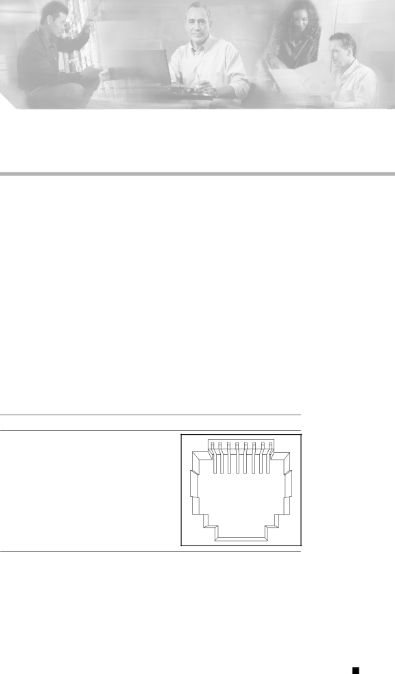
10/100 Ports

The 10/100 Ethernet ports use standard RJ-45 connectors and Ethernet pinouts with internal crossovers. These ports have the send (TD) and receive (RD) signals internally crossed so that a twisted-pair straight-through cable and adapter can be attached to the port. Figure B-1shows the pinout for a 10/100 port.

Figure B-1 10/100 Port Pinouts

Pin Label

1RD+

2RD-

3TD+

4NC

5NC

6TD-

7NC

8NC

1 2 3 4 5 6 7 8

H5318

When connecting 10/100 ports to compatible devices such as servers, workstations, and routers, you can use a two or four twisted-pair straight-through cable wired for 10BASE-T and 100BASE-TX. Figure B-4shows the two twisted-pair straight-through cable schematics. Figure B-6shows the four twisted-pair straight-through cable schematics.

When connecting the ports to other devices, such as switches or repeaters, you can use a two or four twisted-pair crossover cable. Figure B-5shows the two twisted-pair crossover cable schematics. Figure B-7shows the four twisted-pair crossover cable schematics.

Cisco ME 2400 Ethernet Access Switch Hardware Installation Guide


OL-7678-01

B-1


Image 59
Contents Corporate Headquarters Cisco Systems, Inc. All rights reserved N T E N T S Preparing for Installation Crossover Cable and Adapter Pinouts B-5 OL-7678-01 Organization AudiencePurpose Bewaar Deze Instructies ConventionsSäilytä Nämä Ohjeet Guarde Estas Instruções GEM Disse Anvisninger Xii Xiii Related PublicationsProduct Documentation DVD Obtaining DocumentationCisco.com Ordering Documentation Documentation FeedbackCisco Product Security Overview Cisco Technical Support & Documentation Website Reporting Security Problems in Cisco ProductsObtaining Technical Assistance Definitions of Service Request Severity Submitting a Service RequestObtaining Additional Publications and Information Features Setting up the SwitchFront Panel Description 10/100 Ports Front Panel DescriptionsSFP Modules SFP Module SlotsSystem LED LEDsSFP Module Patch Cable Port LEDs Rear Panel DescriptionManagement Options Power ConnectorsCisco ME AC Switch Power Supply Cisco ME DC Switch Power SupplyNetwork Configurations Preparing for Installation Switch InstallationStatement 122F 50C Statement Micron MHz/km Cable Distance Installation GuidelinesGLC-SX-MM Verifying Package Contents Rack-Mounting Verifying Switch OperationInstalling the Switch Powering Off the SwitchRemoving Screws from the Cisco ME Switch Removing Screws from the SwitchRack-Mounting Brackets Attaching Brackets to the SwitchAttaching Brackets to 19-Inch Racks Attaching Brackets for 23-Inch Racks Attaching Brackets to 24-Inch Racks 132665 Attaching Brackets for Etsi Racks 15 Mounting the Cisco ME Switch in a Rack Mounting the Switch in a RackAttaching the Cable Guide Attaching the Brackets to the Switch for Wall-MountingWall-Mounting 18 Mounting the Switch on a Wall Mounting the Switch on a WallTable- or Shelf- Mounting Installing and Removing SFP ModulesInstalling SFP Modules into SFP Module Slots 19 SFP Module with a Bale-Clasp Latch Removing SFP Modules from SFP Module Slots Inserting and Removing the SFP Module Patch Cable 24 Connecting to an Ethernet Port Connecting to the 10/100 PortsConnecting to Fiber-Optic SFP Modules Connecting to SFP Modules26 Connecting to a 1000BASE-T SFP Module Connecting to 1000BASE-T SFP ModulesWhere to Go Next OL-7678-01 Understanding Post Results Diagnosing ProblemsSymptom Possible Cause Resolution Errdisable recovery cause SFP module might be installed Verify that the SFP module is Technical Specifications OL-7678-01 Connector Specifications Connector and Cable SpecificationsSFP Module Ports Figure B-2 Fiber-Optic SFP Module LC ConnectorTwo Twisted-Pair Cable Pinouts Cable and Adapter SpecificationsTP3 Four Twisted-Pair Cable Pinouts for 1000BASE-T PortsAdapter Pinouts Crossover Cable and Adapter PinoutsIdentifying a Crossover Cable Switch Console RJ-45-to-DB-25 Port DTE Connecting to DC Power Preparing the Ground Wire Grounding the SwitchTorque to 15 lbf-in Connecting the Grounding Wire to Earth Ground Wiring the DC-Input Power Source Console Figure C-9 Inserting Wires in the Terminal Block Plug Figure C-10 Torquing the Terminal-Block Captive Screws Figure C-12 Inserting the Terminal Block in the Block Header OL-7678-01 Accessing the CLI Through the Console Port Configuring the Switch with the CLI-Based Setup ProgramTaking Out What You Need Cisco ME DC switch DC power cordConnecting to the Console Port Starting the Terminal-Emulation Software Figure D-3 Connecting the Switch to a PCIP Settings Connecting to a Power SourceEntering the Initial Configuration Information Completing the Setup Program These choices appear OL-7678-01 Numerics IN-2 IN-3 IN-4 IN-5 IN-6