Gigabyte GA-K8N51PVMT-9-RH user manual Drivers Installation, Install Chipset Drivers

Page 49

Chapter 3Drivers Installation

Pictures below are shown in Windows XP.

Insert the driver CD-title that came with your motherboard into your CD-ROM drive, the driver CD-title will auto start and show the installation guide. If not, please double click the CD-ROM device icon in "My computer", and execute the Setup.exe.

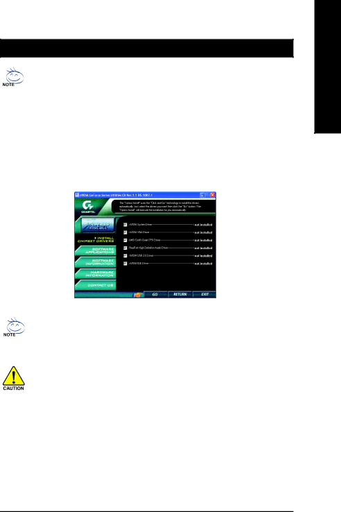
3-1 Install Chipset Drivers

After insert the driver CD, "Xpress Install" will scan automatically the system and then list all the drivers that recommended to install. The "Xpress Install" uses the"Click and Go" technology to install the drivers automatically. Just select the drivers you want then click the "GO" button. The "Xpress Install" will execute the installation for you automatically.

Some device drivers will restart your system automatically. After restarting your system the "Xpress Install" will continue to install other drivers.

System will reboot automatically after install the drivers, afterward you can install others application.

For USB2.0 driver support under Windows XP operating system, please use Windows Service Pack. After install Windows Service Pack, it will show a question mark "?" in "Universal Serial Bus controller" under "Device Manager". Please remove the question mark and restart the system (System will auto-detect the right USB2.0 driver).

English

- 49 -

Drivers Installation

Image 49
Contents GA-K8N51PVMT-9-RH Motherboard Product Manual Classification CopyrightTable of Contents Drivers Installation GA-K8N51PVMT-9-RH Motherboard Layout Block Diagram Page Installation Notices Considerations Prior to InstallationInstances of Non-Warranty Preparing Your ComputerLAN Feature Summary4Mbit flash ROM Installation of the CPU Installation of the CPU and CPU CoolerInstallation of the CPU Cooler Installation of Memory Dual Channel Memory Configuration Installation of Expansion Cards I/O Back Panel Introduction Svid OUT Connectors Introduction ATX12V / ATX Power Connector FDD FDD Connector Cpufan / Sysfan Cooler Fan Power ConnectorSATAII0/1/2/3 Sata 3Gb/s Connectors, Controlled by nForce IDE1 / IDE2 IDE ConnectorBattery Fpanel Front Panel Jumper Cdin CD In Connector Faudio Front Audio Panel Connector14 F11394 Ieee 1394 Connector USB1 / FUSB2 Front USB ConnectorSpdifio Spdif In/Out Coma Coma ConnectorCI Chassis Intrusion, Case Open Clrcmos Clear CmosMain Menu Status Page Setup Menu / Option Page Setup MenuF12 For Boot Menu Main Menu For example Bios Ver. F3a„ Advanced Bios Features „ Standard Cmos Features„ Power Management Setup „ PnP/PCI ConfigurationTime Standard Cmos FeaturesIDE Channel 0 Master/Slave IDE Channel 1 Master/Slave Drive a Floppy 3 Mode Support for Japan AreaMemory Base MemoryHard Disk Boot Priority Advanced Bios FeaturesFirst / Second / Third Boot Device Boot Up Floppy SeekInit Display First Password CheckFrame Buffer Size Onboard GPUSPP Integrated PeripheralsOn-Chip IDE Channel0 SATA-II 2 Secondary RAIDOn-Chip IDE Channel1 IDE1 Conductor CableParallel Port Mode Onboard LAN Boot ROMOnboard Audio Function Onboard LAN FunctionPower-On by Alarm Power Management SetupPME Event Wake Up Modem Ring OnKB Power on Password Power On By KeyboardPower On By Mouse AC Back FunctionPCI 1 IRQ Assignment PnP/PCI ConfigurationsPC Health Status CPU Smart FAN Control Note Frequency/Voltage Control Load Optimized Defaults Load Fail-Safe DefaultsSet Supervisor/User Password Exit Without Saving Save & Exit SetupEnglish Install Chipset Drivers Drivers InstallationSoftware Information Software ApplicationContact Us Hardware InformationConnecting the Video Output Devices EasyTune 5 Introduction Unique Software UtilitiesUser Interface Overview How to use the Xpress Recovery2 Xpress Recovery2 IntroductionSystem requirements Precautions Main Screen of Xpress Recovery2Limitations Method 1 Q-FlashTMUtility Flash Bios Method IntroductionBefore You Begin Task menu for Dual Bios utility Exploring the Q-FlashTM / Dual Bios utility screenEntering the Q-FlashTMutility Task menu for Q-Flash utilitySteps Using the Q-FlashTMutilityYou can repeat to 4 to flash the backup BIOS, too Part Two FlashTMutility bar Exploring the Q-FlashTMutility screenCongratulation!! You have updated Bios successfully Methods and steps Method 2 @BIOSTM UtilityEnglish Before you begin SPP SCSI-0 Nvidia Mirror Step Save and exit Bios Setup GA-K8N51PVMT-9-RH Motherboard Configuring RAID set in RAID Bios YES Nvidia Making a Sata Driver Disk Cd bootdrv MenuInstalling Sata controller driver during OS installation ENTER=Select F3=Exit Enter= Continue R=Repair F3=Exit Solutions Configuring a bootable RAID array with Microsoft WindowsYES English 5 2- / 4- / 6- / 8- Channel Audio Function Introduction Stereo Speakers Connection and SettingsChannel Audio Setup English English Sound Effect Configuration Troubleshooting English English Taiwan Headquarters Contact UsGigabyte Global Service System