Planar PS5580 user manual Connection of Control Cable

Page 15

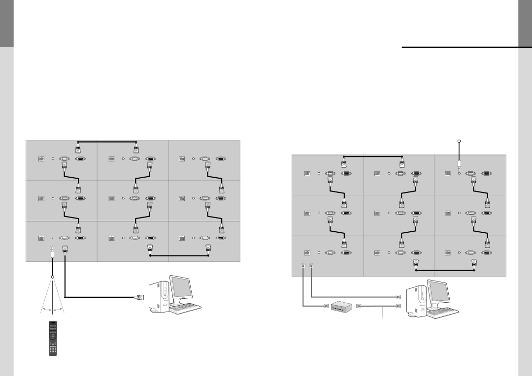
3.6. Connection of Control Cable

Control signal transmission can be connected by 3 different methods.(RS-232C or Ethernet or IR)

RS-232C and Ethernet connection cannot be used simultaneously.

All control signals are output to the RS-232OUT after conversion to RS-232C signal.

3.6.1. Connection of RS-232C Cable & IR Receiver

Maximum use of RS-232C with Daisy Chain connection is 30 sets or less, if you need additional connection, use RS-232C distributor.

LAN

IR

RS232C IN

RS232C OUT

LAN

IR

RS232C IN

RS232C OUT

LAN

IR

RS232C IN

RS232C OUT

LAN

IR

RS232C IN

RS232C OUT

LAN

IR

RS232C IN

RS232C OUT

LAN

IR

RS232C IN

RS232C OUT

LAN

IR

RS232C IN

RS232C OUT

LAN

IR

RS232C IN

RS232C OUT

LAN

IR

RS232C IN

RS232C OUT

IR Receiver


Max. Distance : 7M


RS-232C


20˚


20˚


3.6.2. Connection of Ethernet Cable

In case of Ethernet connection, the control PC should be connected to one of PS5580 sets with Ethernet cable. For the connection between the PS5580 sets, they should be connected with RS-232C cables.

IR Receiver

LAN

IR

RS232C IN

RS232C OUT

LAN

IR

RS232C IN

RS232C OUT

LAN

IR

RS232C IN

RS232C OUT

LAN

IR

RS232C IN

RS232C OUT

LAN

IR

RS232C IN

RS232C OUT

LAN

IR

RS232C IN

RS232C OUT

LAN

IR

RS232C IN

RS232C OUT

LAN

IR

RS232C IN

RS232C OUT

LAN

IR

RS232C IN

RS232C OUT

LAN Cable

LAN Cable (Cross Cable)


(Direct Cable)


POWER

HUB or Router

(Wireless & Cable)

Ethernet control PC

1

2

3

4

5

6

7

8

9


0


OK

RS-232C control PC

RS232

LAN

LAN Cable

(Direct Cable)

- 26 -

- 27 -

Image 15
Contents User’s Manual Supplied Accessories Contents It is recommended to install the set with good ventilation Do not install the set at the air-tight condition※Clearance for Ventilation ※Please keep following PS5580 It always needs two persons to carry or installWhen you carry PS5580 with up straight Panel when you put down the panel※Attention for Installing Safety Precautions Display control via COM port D-Sub 9pin Remote controller input portNames Display control via Ethernet RJ45KEY PAD Connection of Single PS5580 How to Connect CablesConnection of Multiple PS5580 for DP Resolution Output Port Connection RemarkConnection of Multiple PS5580for DVI Connection of Control Cable How to use Remote Controller Configuration Sharpness BrightnessContrast Back LightColor Temperature TintColor Select Color Balance from Picture Menu Adjust Color BalanceColor Balance Gamma SelectionColor Space Picture ResetSelect V Position from Screen menu PositionSelect H Position from Screen menu Select Screen MenuClock Screen ResetSelect Auto Adjust from Setup a menu Select Setup a Menu‚ Each of the value can be adjusted by pressing buttons Select Auto Power from Setup a menu Power SaveAuto Power Select Power Save from Setup a menuLanguage Setup a ResetSelect Language from Setup a menu Select Setup a Reset from Setup a menuKEY Lock Select KEY Lock from Setup a menuSetup the KEY Lock Select Setup B MenuSerial Control LAN SettingOSD Select OSD from Setup B menuSetup the function Setup the turn off timeSelect Rotation from OSD menu Setup the RotationSelect OSD H Positiion Select OSD V PositiionSelect Transparency from OSD menu Setup the Info DisplaySetup the Transparency Select Info Display from OSD menuSetup the OFF Timer OFF TimerSetup B Reset Select OFF Timer from Setup B menuSelect Option menu Factory ResetSelect Factory Reset from Setup B menu Sub-menus can be configuredChange Security Password Input ResolutionGroup ID Tiling Menu LockSelect IR Control from Option menu Setup the Tiling Select the IR ContolIR Control TilingPower on Input Detect Power on DelayNo image at upper and lower part of the screen Before calling for serviceApplicable signals Tick sound from the main bodyEN61000-3-2 SpecificationRegulatory Information EN61000-4-8 Magnetic Field Immunity EN61000-4-11Memo Dimension
Related manuals
Manual 21 pages 13.77 Kb Manual 38 pages 53.75 Kb