3. Drive Unit
A. Belts
1)Open the top cover.
2)Remove the rear cover.
B. Gears
1)Open the top cover.
2)Remove the rear cover.
3)Disconnect the connector to remove the drive unit.
4. Other Parts
A. Sensors
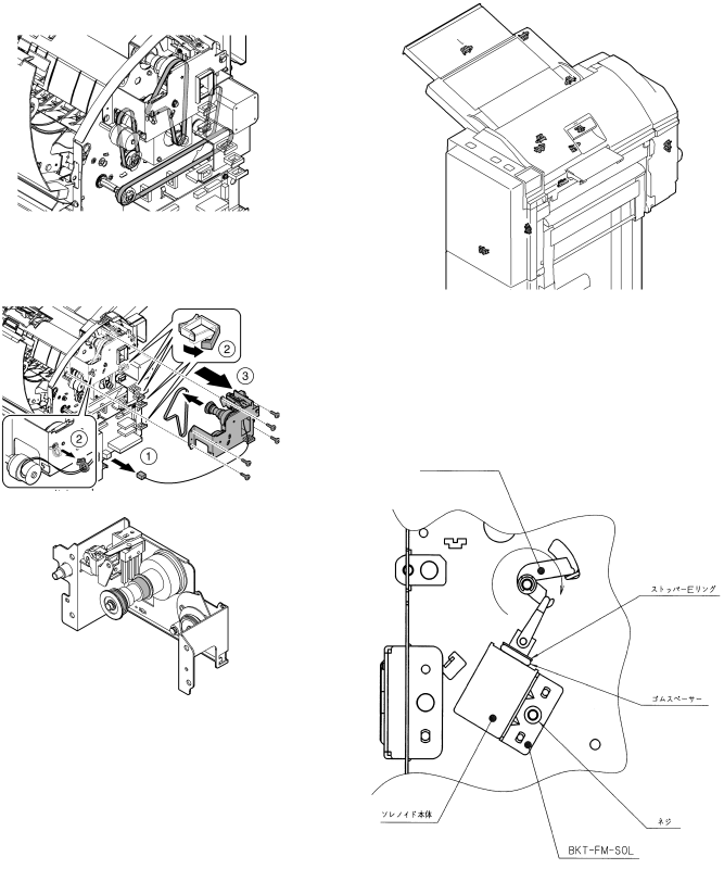
5. Note on assembly
A. Reverse flapper solenoid adjustment
1)Rotate the solenoid lever
2)Adjust the position of the bracket
Stopper
Rubber spacer
Solenoid |
|
|
|
|
main unit |
|
|
|
|
|
|
| Screw | |
|
|
|
| |
|
| |||
|
|
| ||