RuggedCom Understanding Serial Console and WAN Port Configuration for RX1501

Page 25

3. Installation

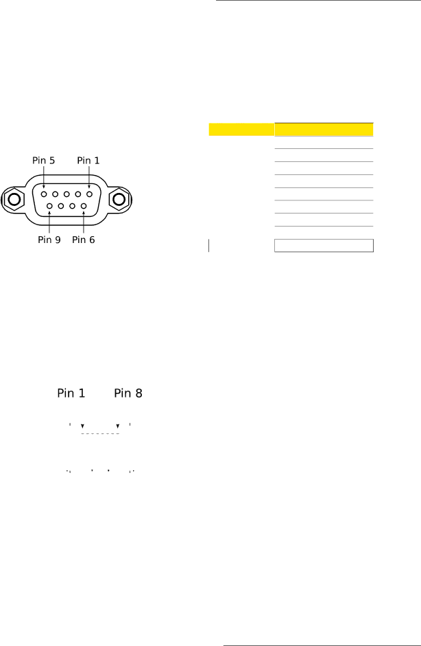
3.4. Serial Console Port

The serial console port on the front panel provides access to the boot-time control and configuration menu interface, and a console interface to the ROX™ operating system.

The serial ports implement RS232 DCE on a female DB9 connector. Serial settings are: 57600 bps, 8 bits, No parity, 1 stop bit. See the illustration and table below for pin configuration and assignment.


DB9 Pin

Signal Function


1

NC


2

TX


3

RX


4

NC


5

GND


6

NC


7

NC


8

NC


9

NC

Figure 3.16. DB9 Serial Console Port

Table 3.1. DB9 Serial Console Pinout

3.5. WAN Ports: RJ45

The RX1501 supports T1/E1 WAN ports, to interface to standard T1 or E1 telecommunication infrastructure. Carefully note the orientation of the RJ45 receptacle when inserting or removing cabling. See the illustration and table below for pin configuration and assignment.


T1/E1 pinout


Pin


Description


1


RRING


2


RTIP


3


NC


4


TRING


5


TTIP


6


NC


7


NC


8


NC


Figure 3.17. RJ45 T1/E1 Pin Configuration

Table 3.2. RJ45 T1/E1 Pin Assignment

RuggedCom® RuggedBackbone™

25

RX1501 Installation Guide Rev 104

Image 25
Contents RuggedBackbone RX1501 All Rights Reserved Warranty Contacting RuggedComDisclaimer Of Liability Registered TrademarksTable of Contents Page List of Figures Page List of Tables FCC Statement And Cautions Product Overview Feature HighlightsFunctional Overview WAN Universal Power Supply Options LM1 through LM6 RuggedBackbone ModulesModule Status LEDs Front PanelPurpose Description PM1Ethernet Copper Line Modules LMEthernet Fiber WAN SFP ModularSerial Cellular ModemAPE Appplication Processing Engine DDS Digital Data Services27. Pluggable terminal block power module HIP module shown Power SupplyRack Mounting Dimensions InstallationRack Mounting RX1501Rack Mounting Dimensions Top View Panel and DIN Rail Mounting Installing Panel and DIN Rail Mounting BracketsPanel and DIN Rail Mounting Dimensions Panel and DIN Rail Mounting Dimensions Connectors for HI and HIP Power Modules Power Supply Wiring and Grounding Connectors for 24, 24P, 48, and 48P Power Modules Chassis Ground Connection AC Power Supply Wiring ExampleDC Power Supply Wiring Example Critical Alarm WiringWAN Ports RJ45 Serial Console PortDB9 Pin T1/E1 pinoutCopper Ethernet Ports WAN Ports BNC1. RJ45 Twisted-Pair Copper Ports Gigabit Ethernet 1000Base-TX Cabling RecommendationsCabling Category 1000Base Required Action Transient SuppressionSerial Ports RJ45 Pin RS232 Mode RS485 Mode RS422 ModeDDS Ports RJ45 RJ45 Pin DescriptionDDS Rx and Tx LED Indications SFP Optics Installation, removal, and precautionsRx LED Color Status Tx LED Color StatusSFP Module Removal Module Insertion SFP25. SFP module removal Fiber Ethernet PortsModule Order Code Description Cellular ModemsGSM, EDGE, HSPA+ Cellular Modem Card Installing SIM Cards for GSM, EDGE, HSPA+ Cellular ModemsPage APE Application Processing Engine Feature DescriptionAPE Overview Supported Operating SystemsPlacing the APE in a Vlan Secondary Network InterfaceProcedure 3.1. To install an operating system Installing an Operating SystemResetting the Module APE BiosLED Indicators LED Color and StateFAQs Power Supply Specifications Technical SpecificationsCritical Alarm Relay Specifications Copper Ethernet Port SpecificationsFast Ethernet 100Mbps Optical Specifications Fiber Ethernet Port SpecificationsCable Tx λ typ Tx min Tx max Distance Power OrderGigabit Ethernet 1Gbps Optical Specifications Mechanical SpecificationsOperating Environment Test Description Test Levels Severity EMI And Environmental Type TestsESD Test Description Test Levels Ieee 1613 C37.90.x EMI Immunity Type TestsaAgency Standards Comments Agency ApprovalsRuggedCom Inc Warranty