Abit AW9D-MAX manual 2 DDR2 Memory Slots

Page 20

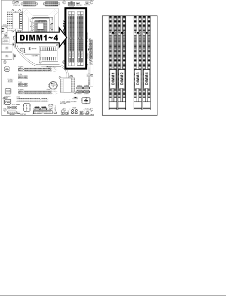
2.5.2 DDR2 Memory Slots

This motherboard provides four 240-pin DIMM slots for Dual Channel DDR2 800/667 memory modules with memory expansion size up to 8GB.

To reach the optimum performance in dual-channel configurations, install identical DDR2 DIMM pairs for each channel.

Install DIMMs with the same CAS latency. To reach the optimum compatibility, obtain memory modules from the same vendor.

Due to chipset resource allocation, the system may detect less than 4GB of system memory in the installation of four 1GB DDR2 memory modules.

There are several methods of different DDR2 configurations depending on how the DIMMs are populated on each system memory channel:

[Single Channel]: only one channel is populated.

Method


Channel A


Channel B

DIMM1


DIMM2

DIMM3


DIMM4


1

512MB


-

-


-

2

-


512MB

-


-

3

-


-

512MB


-

4

-


-

-


512MB

5

512MB


512MB

-


-

6

-


-

512MB


512MB

2-12

AW9D-MAX, AW9D

Image 20
Contents AW9D-MAX AW9D Motherboard SocketAW9D-MAX, AW9D Contents Driver & Utility CD Features & Specifications IntroductionIeee 1394 For model AW9D-MAX only Motherboard Layout 1 AW9D-MAX Introduction2 AW9D Installing Motherboard Choosing a Computer ChassisChecking Jumper Settings Short OpenCmos Memory Clearing Header and Backup Battery AW9D-MAX, AW9D Wake-up Header USB-PWR1Connecting Chassis Components ATX Power ConnectorsFront Panel Switches & Indicators Headers FAN Power Connectors Installing Hardware CPU SocketAW9D-MAX, AW9D Hardware Setup 2 DDR2 Memory Slots 256MB 512MB PCI Express X16 Add-on Slots Install Graphics Card Hardware Setup AudioMAX Connection Slot HD Audio AW9D-MAX, AW9D Connecting Peripheral Devices Floppy and IDE Disk Drive Connectors Hardware SetupSerial ATA Connectors Additional IEEE1394 Port Header Additional USB 2.0 Port HeadersHardware PCI Express X1 Add-on Slots PCI Add-on SlotGuru Panel Connection Header Onboard Indicators and Buttons Post Code DisplayerPower Source Indicators Onboard Buttons Connecting Rear Panel I/O Devices AW9DAW9D-MAX, AW9D Bios Setup ΜGuru Utility OC GuruBios Setup Power Cycle Statistics Click Enter key to enter its submenu Abit EQTemperature Monitoring Voltage Monitoring Fan Speed Monitoring FanEQ Control 1st FanEQ Group2nd FanEQ Group Click Enter key to enter its submenu 2nd FanEQ Group3rd FanEQ Group Click Enter key to enter its submenu 3rd FanEQ GroupStandard Cmos Features Click Enter key to enter its submenu Back to Standard Cmos Features Setup Menu Advanced Bios Features IDE CdromCPU Feature Back to Advanced Bios Features Setup Menu Bios Setup Advanced Chipset Features Back to Advanced Chipset Features Setup Menu PCI Express Root Port FuncIntegrated Peripherals On-Chip IDE DeviceSata RAID ROM On-Chip PCI Device Super-IO Device Onboard PCI Device Bios Setup Power Management Setup AcpiWake Up by WAKE# of PCIe AW9D-MAX, AW9D PnP/PCI Configurations IRQ-4 Load Fail-Safe Defaults Load Optimized DefaultsSet Password Save & Exit SetupAW9D-MAX, AW9D Driver & Utility CD Intel Chipset Software Installation Utility Intel Matrix Storage Technology Driver Realtek Audio Driver Realtek LAN Driver Silicon Image 3132 Sata Driver Silicon Image 3132 Sata RAID Driver USB 2.0 Driver Abit µGuru UtilityIntel Sata RAID Driver Disk Maker Utility CD10 Sil3132 Sata RAID Driver Disk Maker Post Code Definitions Award Post Code DefinitionsEarly PCI Initialization Auto 2 AC2005 Post Code Definitions Troubleshooting How to Get Technical Support? 1 Q & aAW9D-MAX, AW9D Appendix Technical Support Form Universal Abit Contact Information Sales sales@abit.com.tw Marketing market@abit.com.twRev