with a 12 volt DC signal using a 560 ohm, ¼-watt resistor in series with the connec- tion would be appropriate. With a 24 volt DC control signal a series resistor of 1.8 k (1800) ohm is recommended. For correct operation a minimum current of 2 milliam- peres is recommended.
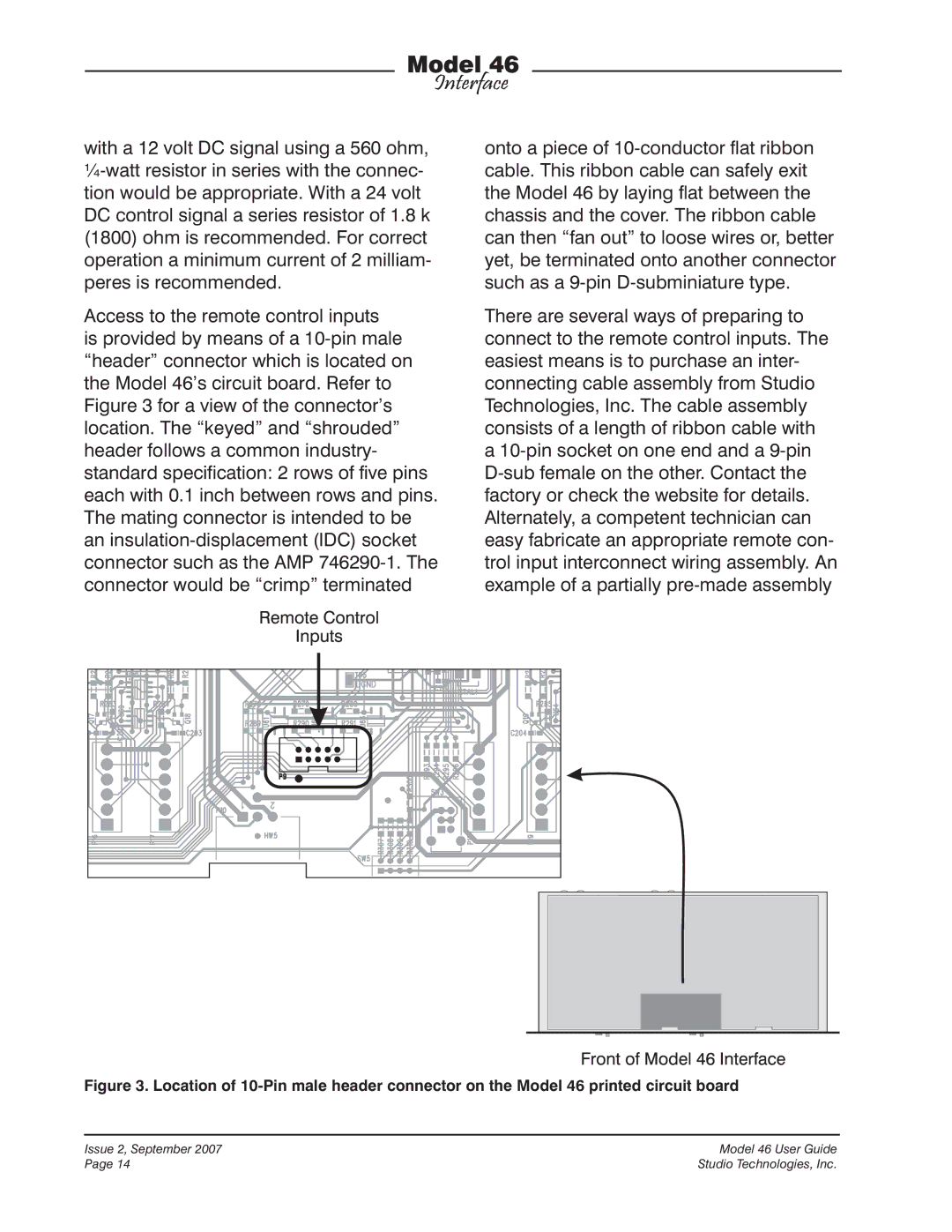
Access to the remote control inputs is provided by means of a 10-pin male “header” connector which is located on the Model 46’s circuit board. Refer to Figure 3 for a view of the connector’s location. The “keyed” and “shrouded” header follows a common industry- standard specification: 2 rows of five pins each with 0.1 inch between rows and pins. The mating connector is intended to be an insulation-displacement (IDC) socket connector such as the AMP 746290-1. The connector would be “crimp” terminated
onto a piece of 10-conductor flat ribbon cable. This ribbon cable can safely exit the Model 46 by laying flat between the chassis and the cover. The ribbon cable can then “fan out” to loose wires or, better yet, be terminated onto another connector such as a 9-pin D-subminiature type.
There are several ways of preparing to connect to the remote control inputs. The easiest means is to purchase an inter- connecting cable assembly from Studio Technologies, Inc. The cable assembly consists of a length of ribbon cable with a 10-pin socket on one end and a 9-pin D-sub female on the other. Contact the factory or check the website for details. Alternately, a competent technician can easy fabricate an appropriate remote con- trol input interconnect wiring assembly. An example of a partially pre-made assembly
Figure 3. Location of 10-Pin male header connector on the Model 46 printed circuit board
Issue 2, September 2007 | Model 46 User Guide |
Page 14 | Studio Technologies, Inc. |