are especially sensitive to this requirement. The Model 46’s sophisticated auto nulling function uses analog circuitry under mi- croprocessor control to achieve significant trans-hybrid loss. This return-loss “null” is achieved by making a series of adjustments to account for the resistive, inductive, and capacitive conditions that are present on the connected 2-wire party-line circuit. The party-line’s conditions are the sum of the impact made by the type and quantity of cable, the connected user-devices, and the intercom power source.
Whenever a user presses one of the Model 46’s “auto null” buttons digital circuitry ad- justs the analog hybrids to rapidly achieve their maximum return-loss. The nulling pro- cess takes less than 10 seconds for each channel of an interface. However, it’s impor- tant to note that while the nulling process is automatic, it only takes place upon user request. This can lead to more stable and consistent audio performance when a hy- brid is exposed to the varying 2-wire condi- tions often found in broadcast applications. The parameters obtained during the nulling process are stored in non-volatile memory; mains power interruptions won’t require the auto nulling function to again be performed.
A sine-wave audio tone is generated for use during the auto nulling process. The frequency is software-controlled to maxi- mize the ability of the hybrid circuits to reach a “deep” null. In addition, at the beginning of each auto null sequence a short period of 24 kHz tone is sent to the associated 2-wire party-line interface. This serves as a microphone disable (“mic kill”) signal for user devices such as the RTS BP325. By automatically disabling “open” microphones the auto nulling process can achieve better performance.
4-Wire Interfaces
Associated with the 4-wire portion of the Model 46’s interfaces are analog line-level inputs and outputs. These are intended to interconnect with a variety of 4-wire de- vices, including matrix intercom systems, audio-over-fiber transmission systems, and other specialized audio equipment. The input and output circuitry is transform- er-coupled to minimize the chance of hum, noise, or ground “loop” issues.
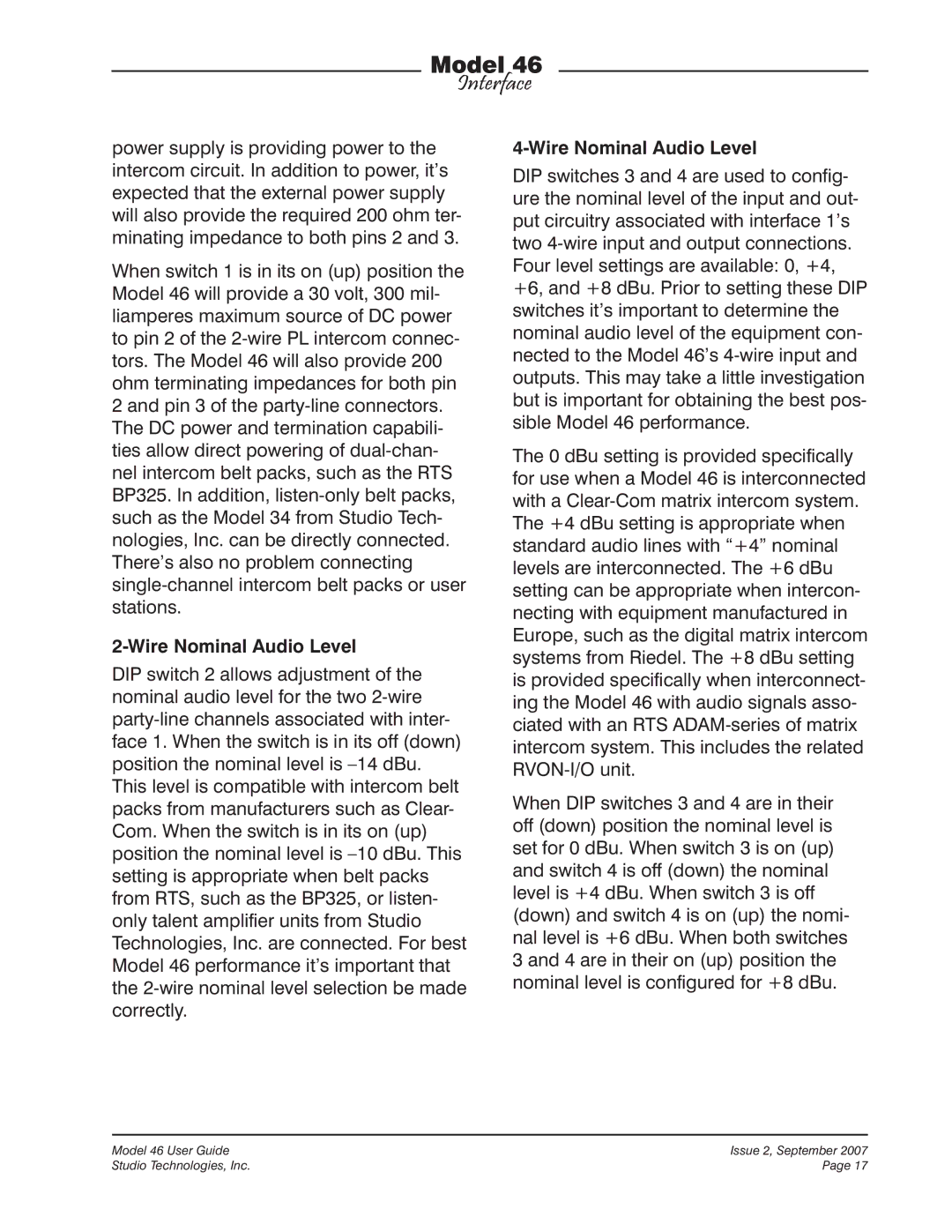
A key characteristic of the Model 46’s de- sign is the ability to select the 4-wire input and output nominal levels. This helps to ensure compatibility with virtually all audio equipment. Front-panel-accessible DIP switches allow the nominal levels to be configured from among four choices: 0, +4, +6, or +8 dBu. The 0 dBu setting was specifically provided for compatibility with Clear-Com matrix intercom systems. The +4 dBu setting allows “standard” audio signals to be directly connected. Digital matrix intercom systems from Riedel® can be effectively connected using the +6 dBu setting. And the +8 dBu setting allows proper level matching with the popular ADAM™ series of matrix intercom systems from Telex/RTS. This setting also applies to the related RVON-I/O VoIP product.
The Model 46 contains eight 5-segment LED level meters. Four of the meters are provided for each interface, with two displaying the level of the signal being received from the 4-wire source and two displaying the level being sent to the 4-wire output. During installation and setup the meters are invaluable in help- ing to confirm that the nominal level DIP switch settings have been properly made. During normal operation the meters offer rapid confirmation of audio signal flow in