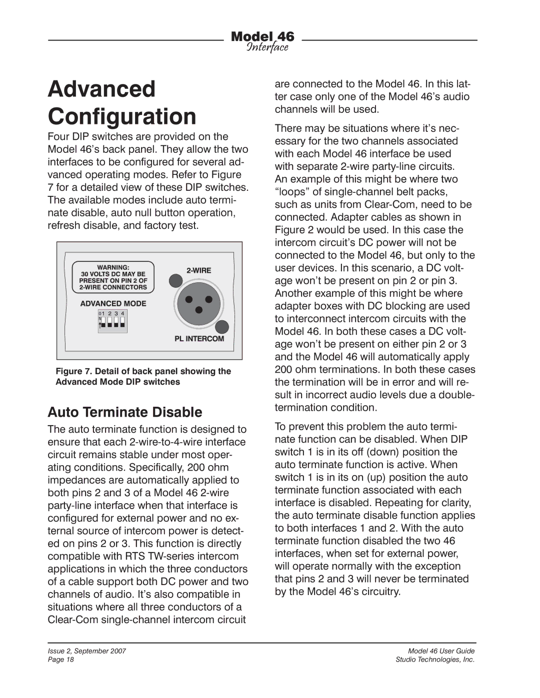
longer passing through this component and on to the 4-wire audio output. When- ever this situation arose the component was not damaged, but restoring the flow of audio required either a power down/power up sequence, an auto null operation, or a change to one of the level configuration DIP switches to take place. While it is very unlikely that this type of ESD event would occur during normal field operation it is of concern for critical Model 46 applications. To minimize the chance that the audio path could experience this problem a “refresh” routine was added to the Model 46’s operating software (“firmware”). To ensure that the ESD-sensitive component always remains functioning correctly the software resends its operating instructions four times each second. With this imple- mentation the worst case scenario would result in an audio loss of 250 milliseconds or less in the event of an extreme ESD “hit” being experienced.
But nothing comes without a price and in this case the refresh routine adds a very slight audio “tick” to the 4-wire output and 2-wire party-line signals. During typical applications these refresh “ticks” will not be noticeable. But there may be situa- tions where any added audio artifact may simply not be acceptable. To address this possible, but highly unlikely, case back- panel DIP switch 3 can be used to disable the refresh routine. When switch 3 is in its off (down) position the Model 46 operates in its standard fashion. When switch 3 is in its on (up) position the refresh routine is disabled. The Model 46 will continue to function normally with the exception that the four-times-per-second component refresh routine will not occur. Goodbye “click” but hello to the possibility that an
ESD-induced audio path problem could occur. A good “rule of thumb” is that if a Model 46 is mounted in an equipment rack with a known-good ground connection, disabling refresh shouldn’t pose any risk to reliable operation. But if a unit is mount- ed in a portable rack, or used loose as a single device, refresh should always remain enabled. The reasoning is quite simple: the latter condition is much more likely to allow an ESD “hit” to dissipate into the Model 46’s enclosure, while a substantial rack enclosure will offer a low-impedance path for ESD energy to dissipate into.
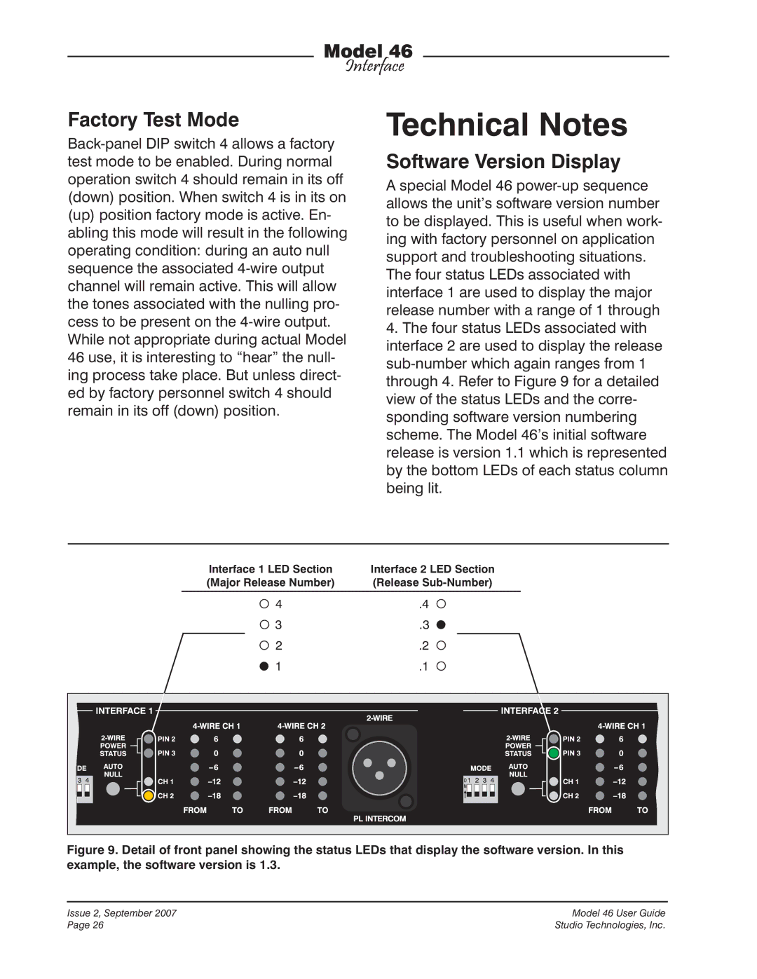
Factory Test
Back-panel DIP switch 4 is used to select between normal mode and factory test mode. When switch 4 is in its off (down) position the Model 46 operates in its stan- dard fashion. When switch 4 is in its on (up) position the factory test mode is selected. As expected, when the Model 46 is de- ployed in the field switch 4 should remain in its off (down) position. No damage to the Model 46 or connected equipment will occur when factory test mode is active.
Operation
Technician intervention is typically not required during normal Model 46 operation. The unit is designed for continuous opera- tion with no routine maintenance necessary. Activating the auto null functions may be warranted should connected user devices or wiring associated with the 2-wire party- line intercom be changed. Upon power-up the Model 46 will go through a short initial- ization sequence before normal operation will begin. The power and status LEDs
will each light sequentially and, upon