StudioTech M46-00180 manual Advanced Operation, Auto Terminate Disable

Page 25

active microphones. While the automatic “mic kill” signal will apply to many user devices it may not apply to all. Muting microphones is significant as obtaining a “deep” null requires that no extraneous signals be present on the intercom circuit.

Advanced

Operation

The Model 46 allows several of the operat- ing parameters to be configured to meet the needs of specific applications. The following paragraphs provide details about the auto terminate disable and factory test modes.

Auto Terminate Disable

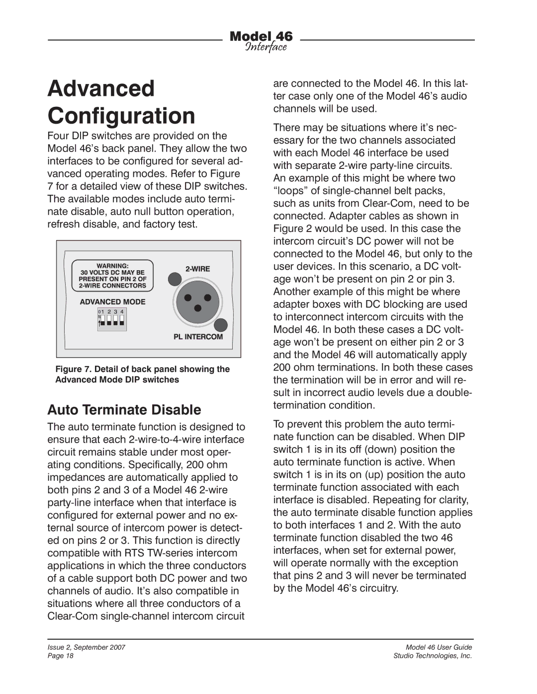
As previously discussed in this user guide, the auto terminate function can come into play when a 2-wire interface is configured for external power. Using a combination of hardware and software, pins 2 and 3 of each 2-wire PL intercom connector are monitored for the presence of DC voltage. If a level of greater than approximately

18 volts DC is not detected on either pin,

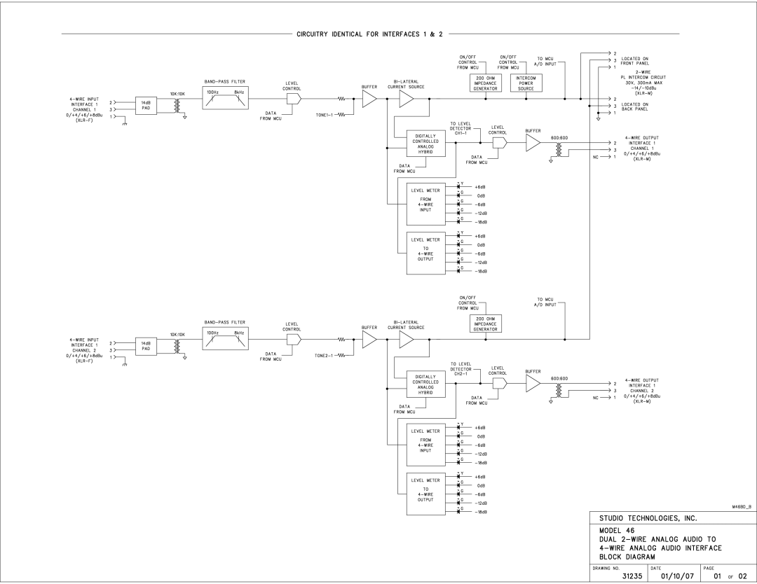
200 ohm terminating networks are applied to those same pins. This ensures that the Model 46’s hybrid circuitry remains stable, preventing objectionable audio signals from being sent to the 4-wire output con- nectors. One caveat does apply; there may be a few seconds of severe noise whenever an interface moves from a DC present condition to a DC not present condition. But other than that period, the audio paths will remain “clean.”

As a visual aid, LEDs on the front panel will display the DC power status of pins

2 and 3. But when auto terminate disable mode is active the LEDs will no longer indicate the intercom circuit’s termination status.

For special externally powered 2-wire ap- plications the auto terminate function can be disabled. This primarily will come into play when “splitting” the Model 46’s re- sources into four separate single-channel interfaces. Moving advanced configuration DIP switch 1, located on the Model 46’s back panel, to its on (up) position disables the auto terminate function. To someone observing only the Model 46’s front panel this change would not be readily appar- ent. The front-panel LEDs will continue to display the DC power status of pins 2 and

3.But whether or not either or both LEDs are lit, the Model 46 will never apply 200 ohm terminations to pins 2 or 3. For the hybrid circuits to remain stable termina- tion impedances must be provided by the connected circuits. If these are not pres- ent one should expect the hybrid circuits to generate a very impolite noise. This condition, caused by the 2-wire output circuitry being in an “unloaded” state, will not damage the Model 46’s circuitry. But errors in cable “patching,” a disconnected cable, or other real-world issues, can lead users listening to signals that originate in the Model 46’s 4-wire outputs from being presented with a rude surprise!

In conclusion, it’s important that technical personnel working with the Model 46 be informed when the auto termination func- tion has been disabled. They will then be aware of the potential noise issues and be ready to make corrections should a prob- lem arise.

Model 46 User Guide

Issue 2, September 2007

Studio Technologies, Inc.

Page 25

Image 25 Contents
User Guide This page intentionally left blank Table of Contents Issue 2, September Model 46 User Guide Introduction Wire InterfacesModel 46 Front Panel Model 46 Back Panel Analog Hybrids with Auto Nulling Wire Interfaces Special Applications Pro Audio QualityDesign Philosophy Simple InstallationWire Audio Inputs and Outputs InstallationSystem Components Locating the ModelDetail of back panel showing line inputs and outputs Wire Line OutputsDual-Channel Intercom Systems Wire Party-Line Intercom ConnectionsSingle-Channel Intercom Systems Adapter cable wiring diagram Remote Control InputsIssue 2, September Model 46 User Guide Function AC Mains PowerConfiguration Interface 1 ConfigurationWire Party-Line Power Source Wire Nominal Audio Level Auto Terminate Disable Advanced ConfigurationAuto Null Button Operation Refresh DisableFactory Test OperationLevel Meters External Power Source Connecting Party-Line DevicesInternal Power Source Detail of front panel showing auto null section Auto NullAdvanced Operation Technical Notes Factory Test ModeSoftware Version Display Model 72 Interface Not a TW-12B ReplacementGeneral Audio SpecificationsAppendix a Appendix B Appendix C