Panasonic AW-DU600 manual Specifications

Page 21

Specifications

Power supply:

DC 10.8V to DC 16V

Power consumption: 5 W

indicates safety information

Permissible temperatures

Storage: j20˚C to 60˚C

Operating: j10˚C to 45˚C

Standard: i5˚C to 35˚C

Permissible humidity

Storage: 30% to 90% (without condensation)

Weight:

3.7lb (1.7 kg) Dimensions (WkHkD):

8-1/4k3-3/8k6-7/8 inch (210k86k176 mm)

Controllers supported

AW-RP301, AW-RP501, AW-RP505, AW-RP605 and WV-CB700A

Pan-tilt heads supported

AW-PH300A, AW-PH350 (this model can only be used with the AW-RP605), AW-PH500 and AW-PH600

Cameras supported

AW-E300, AW-E300A, AW-E600, AW-E800A, AW-E800

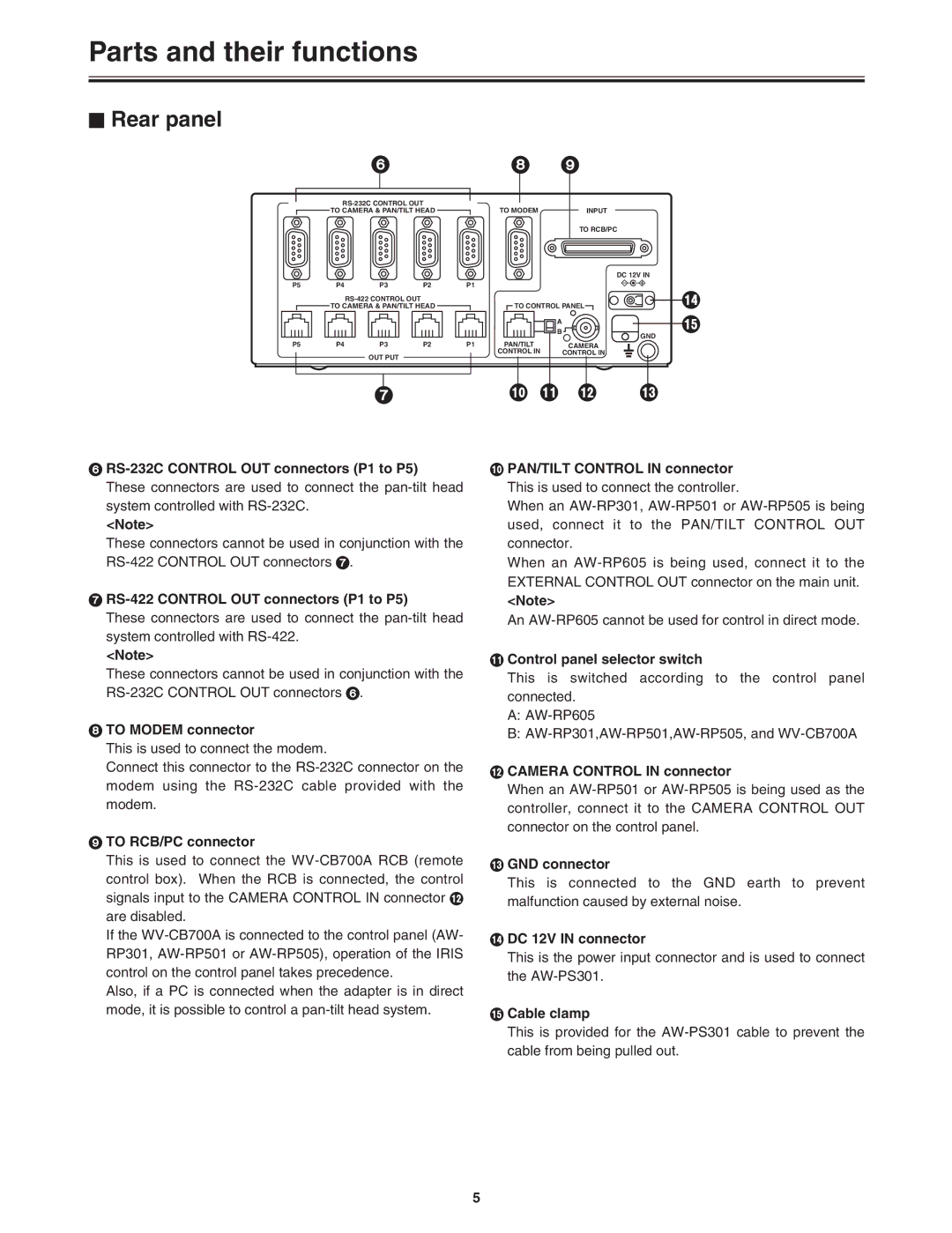
Input connectors DC12V IN socket

Connects the AW-PS301

TO RCB/PC

AW-CA50T10 (when a WV-CB700A is connected) AW-CA50T9 (when a PC is connected)

PAN/TILT CONTROL IN RJ45

Connects to PAN/TILT CONTROL OUT on the remote control panel

10BaseT straight cable (UTP category 5), max. 500 meters

CAMERA CONTROL IN

BNC

Connects to CAMERA CONTROL OUT on the remote control panel

BNC cable (5C-2V), max. 500 meters

Output connectors:

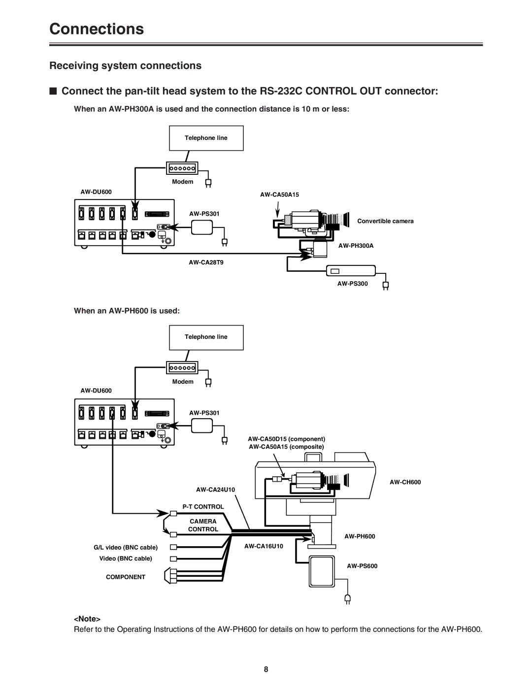
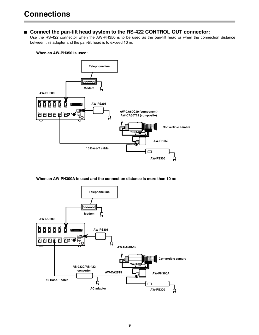
RS-232C CONTROL OUT

TO CAMERA & PAN/TILT HEAD

D-sub, 9-pink5 (connect to pan-tilt head)

RS-422 CONTROL OUT

TO CAMERA & PAN/TILT HEAD

RJ45k5 (connect to pan-tilt head)

10BaseT straight cable (UTP category 5), max. 1000 m

I/O connector

TO MODEM

D-sub, 9-pin k1 (connects to analog modem)

Other

A/B selector switch

Control panel selector switch

A:AW-RP605

B:AW-RP301, AW-RP501, AW-RP505 and WV- CB700A

21

Image 21
Contents Model AW- P FCC Note Contents AccessoriesIntroduction Parts and their functions To Modem connector RS-422 Control OUT connectors P1 to P5To RCB/PC connector Control panel selector switchConnections When an AW-RP605 is usedTransmitting system connections Connect the control panelMenu j Function R e c t Transmitting system connection procedureMenu j N e 0 a n d 9 a n dWhen an AW-PH600 is used When an AW-PH350 is used AC adapter AW-CA16U10 Video BNC cable N u j 1 F u n c t i o n R x D i r e c t Receiving system connection procedureN u j 5 O u t p u t j J 2 3 2 C R S j 4 2 D eMaking a call After entering the telephone number, press the Start keyControl the pan-tilt head system from the control panel Control the pan-tilt head system directly using this adapter $ Direct modeConnection procedure Menuj 5 Output-1 J 2 3 2 C R S j 4 2Menu j Output-2 P 4 P Control the pan-tilt head system using a control panel or PC Menuj Output-1 J 2 3 2 C R S j 4 2 Menuj 4Input J 2 3 2 C R S j 4 2Menu settings $ How to perform menu settings$ Menu items $ Dial memory Changing the position of the rear panel Attaching the rack mounting adaptersAttaching the joint angle adapter Specifications Page Page Panasonic Broadcast & Television Systems Company