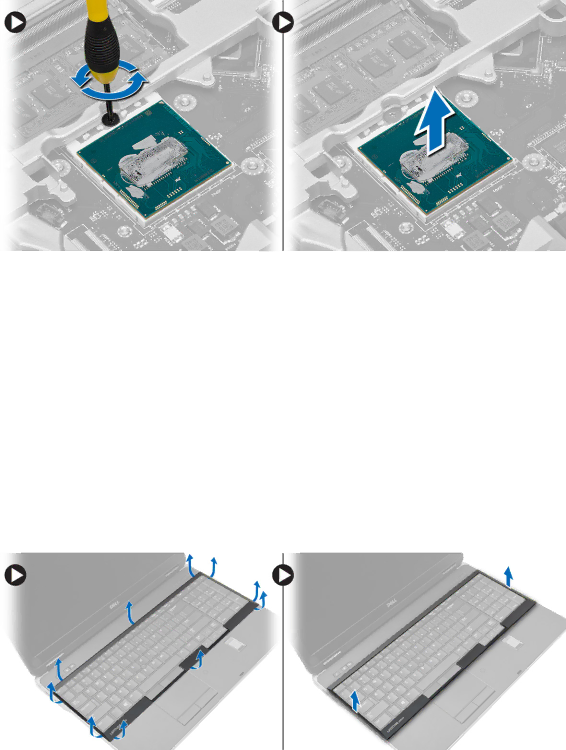
Installing the Processor
1.Align the notches on the processor and the socket, and insert the processor into the socket.
2.Rotate the
3.Install:
a.
b.base cover
c.battery
4.Follow the procedures in After Working Inside Your Computer.
Removing the Keyboard
1.Follow the procedures in Before Working Inside Your Computer.
2.Remove the battery.
3.Using a plastic scribe, pry under the keyboard trim and then along the sides and bottom to release it from the computer. Lift and remove the keyboard trim from the computer.
4.Remove the screws that secure the keyboard to the palmrest assembly, lift and flip the keyboard to access the
25