7
HI-EFFICIENCY HEATING
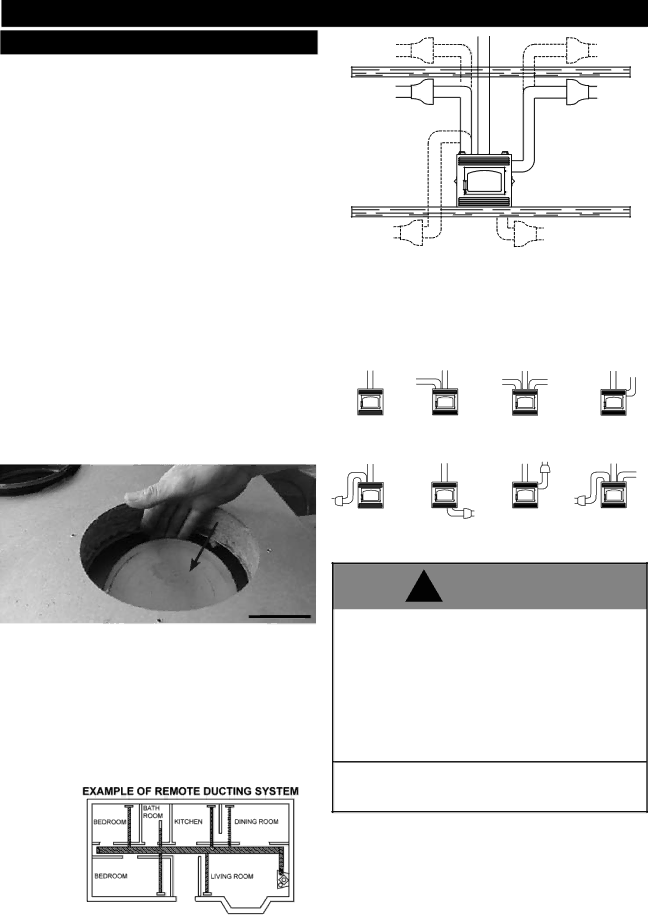
FIVE OPTIONS
To operate this
A BLOWER KIT (NZ62) This blower is installed in the bottom of the unit and used to direct the heat into the room where the fi replace is lo- cated. The blower is controlled, by a variable speed switch, located inside the fi replace.
| ATTIC |
| OPTION |
BLOWER | FOR |
TYING | |
LOCATION | INTO |
OPTIONS | EXISTING |
| DUCT |
| WORK |
A THERMOSTATIC AIR CONTROL (NZ690KT) may be used for constant heat, complete with automatic damper and thermostat, wall mounted in the room containing the fi replace, and at least 10 feet (minimum) from the fireplace.
A HOT AIR GRAVITY VENT SYSTEM (NZ220) may be used to distribute heat to an adjoining room (located either above, or beside the room containing the fi replace) by way of vents, eliminating the need of an additional blower. While this system may be used in conjunction with the optional blowers, it could reduce the fl ow of hot air being distributed to additional rooms. It must be experimented with and the dampers adjusted manually to suit your requirements. This may take a few attempts; thereafter adjustments should no longer be required as is normally experienced with your central heating system registers.
The heat shield cover plate must be removed before installing the gravity vent. The hot air vent must be installed in an upward direction! NEVER install in a downward direction. Figure 6. The hot air gravity vent system is not to be connected to a central heating system (for this application use the NZ62CH). This option may not be used in mobile homes.
No more than two hot air gravity vents can be installed to fi replace. Individual vent runs are not to exceed 10 feet.
All hot air gravity vents must be insulated.
FIGURE 5b
A HOT AIR DISTRIBUTION KIT
These options may be incorporated with one another. If the optional blowers are to be installed, make provision during framing to route a 110 volt power line to the fi replace. Detailed installation instructions are included with each venting kit.
NO | GRAVITY VENT | GRAVITY VENT |
|
DUCTING | OPTION (1 DUCT) | OPTION (2 DUCTS) | GRAVITY VENT OPTION |
*RIGHTONLYSIDE
| CENTRAL HEATING |
| CENTRAL HEATING & |
CENTRAL HEATING | BOTTOM | CENTRAL HEATING | GRAVITY VENT OPTION |
HEAT SHIELD COVER PLATE
*MASONRY APPLICATION ONLY
FIGURE 6
STOVE TOP
FIGURE 4
A CENTRAL HEATING SYSTEM (NZ62CH) may be used to heat rooms up to 50 feet from the unit. A wall mounted thermostat located in the room to be heated controls the blower supplying warm air from the room containing the fi replace. If a hot air duct system exists, the central heat blower may safely be tied into this system to reduce the amount of new ducting required. Consult with a heating specialist to ensure a proper duct layout for your home. If the NZ62CH is installed at the bottom of the unit, it could introduce a cool draft into the room that the fi replace is installed in.
When attached to the top or sides of the unit, it provides a higher heat output. This option may not be used in mobile homes.
FIGURE 5a
!WARNING
Do not draw outside air from garage spaces. Exhaust products of gasoline engines are hazardous.
Do not install outside air ducts such that the air my be drawn from attic spaces, basements or above the roofi ng where other heat- ing appliances or fans and chimneys exhaust or utilize air. These precautions will reduce the possibility of fi replace smoking or air
flow reversal. The outside air inlet must remain clear of leaves, debris ice and/or snow. It must be unrestricted while unit is in use to prevent room air starvation which can cause smoke spillage and an inability to maintain a fi re. Smoke spillage can also set off smoke alarms.
To prevent contact with sagging or loose insulation, the fi replace must not be installed against vapour barriers or exposed insulation. Localized overheating could occur and a fi re could result.
NorthlineExpress.com | http://www.northlineexpress.com |