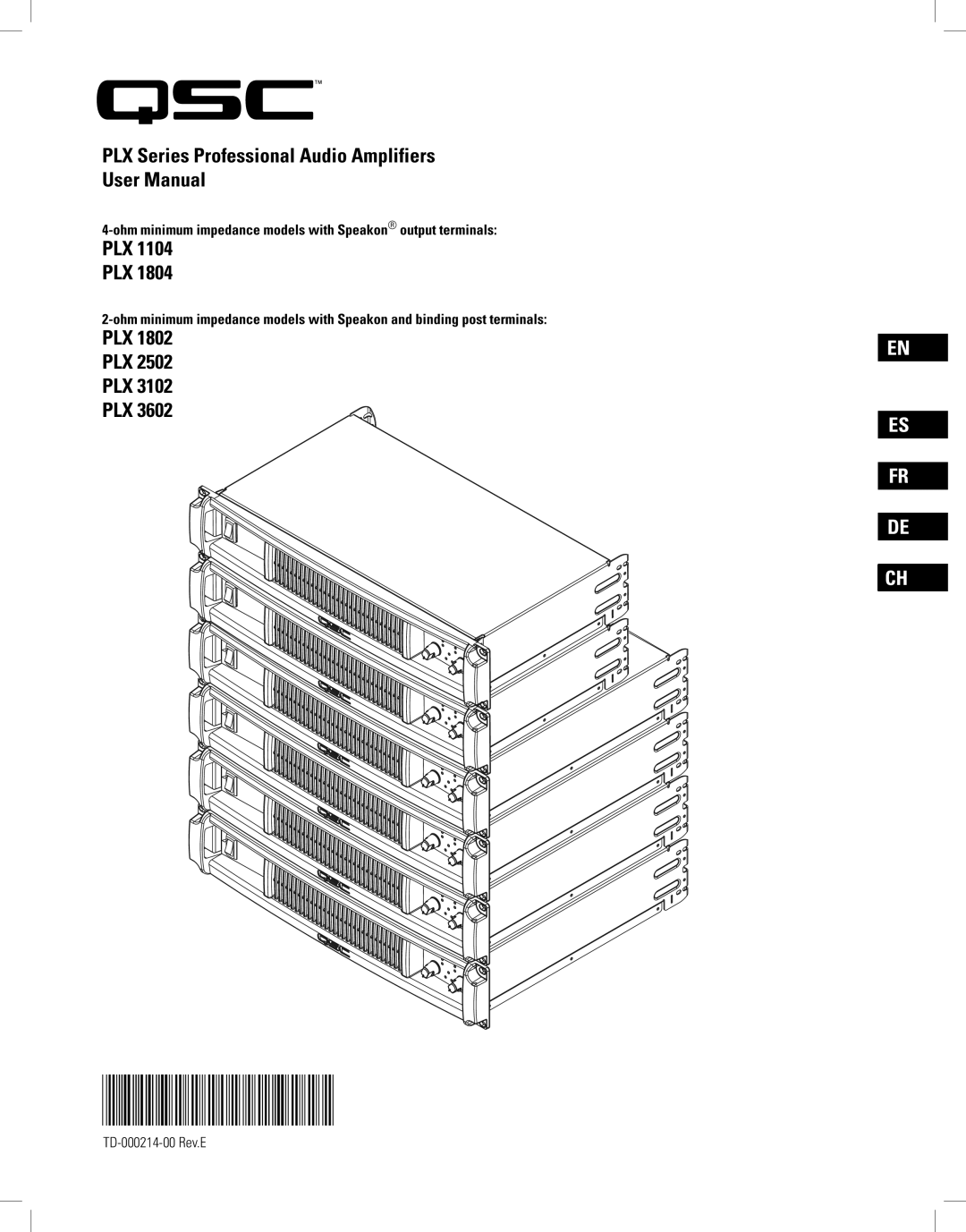
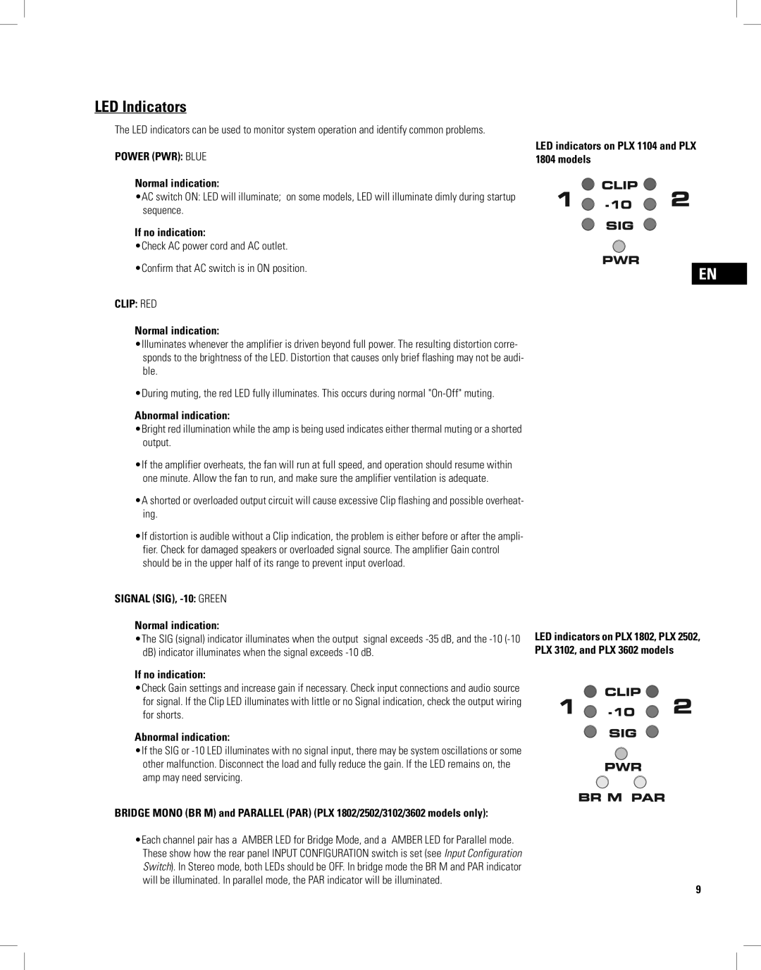
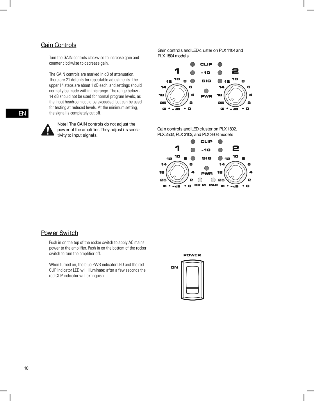
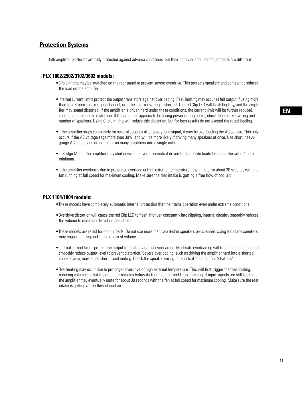
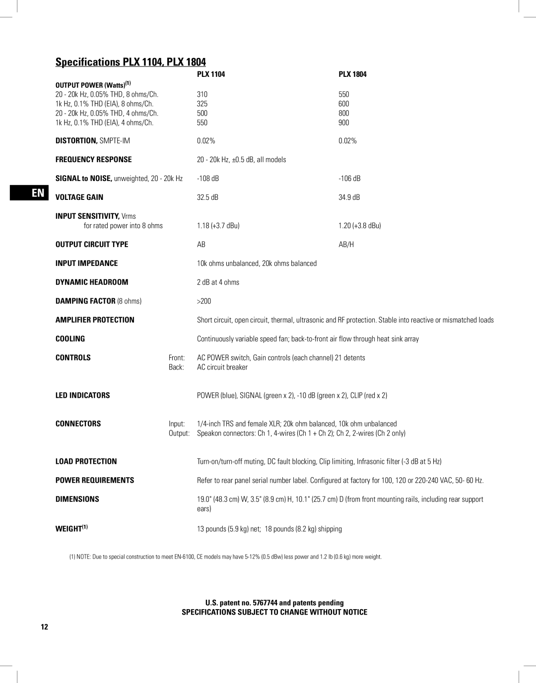
PLX1802, PLX3102, PLX3602, PLX1804, PLX2502 specifications
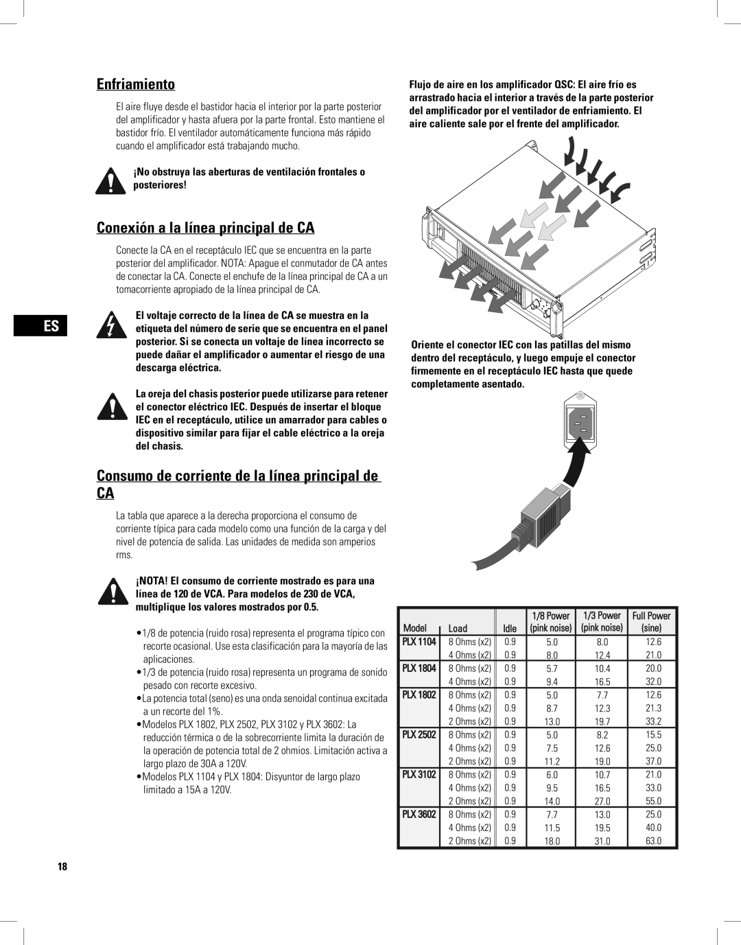
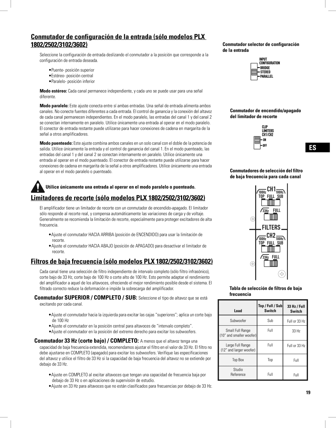
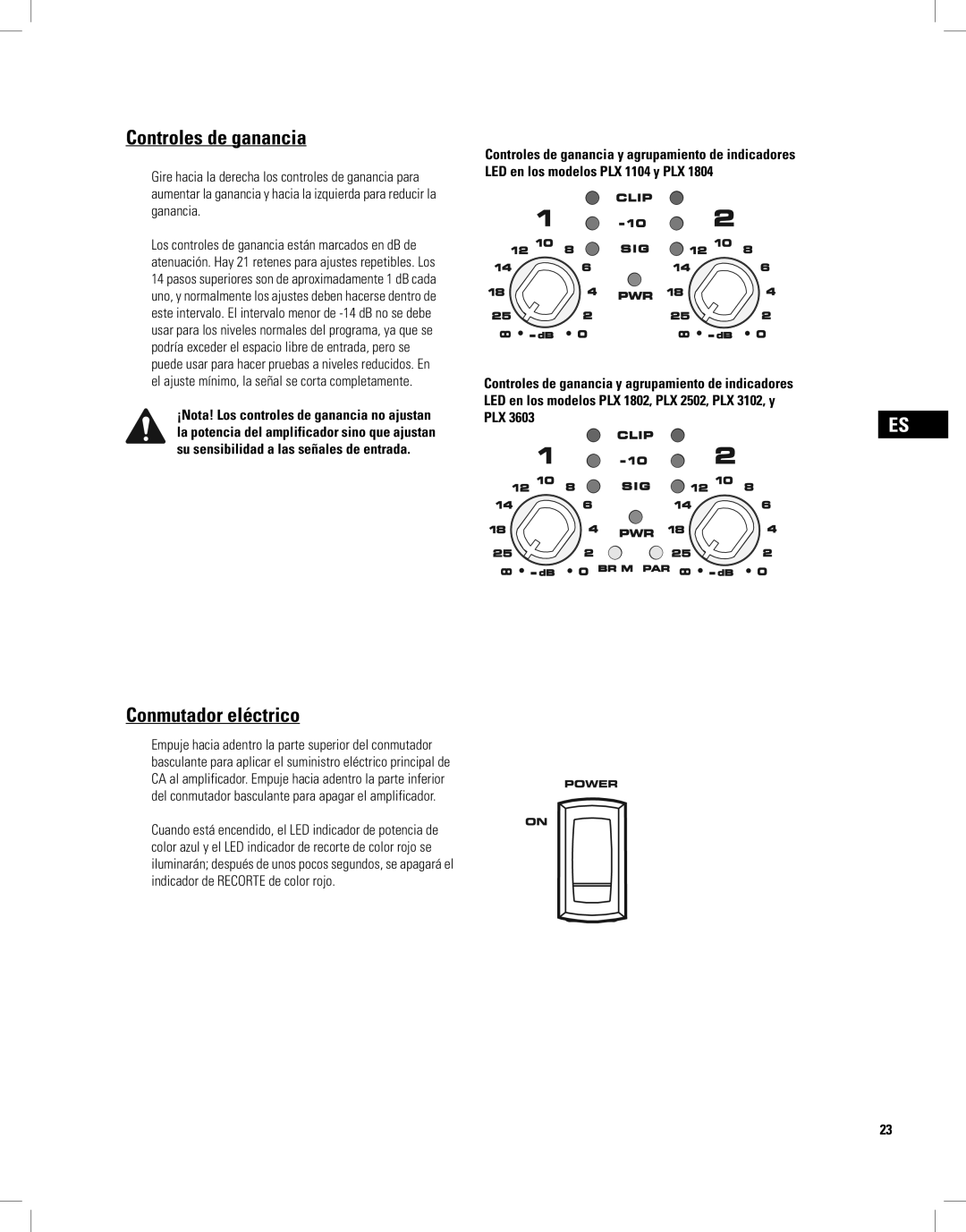
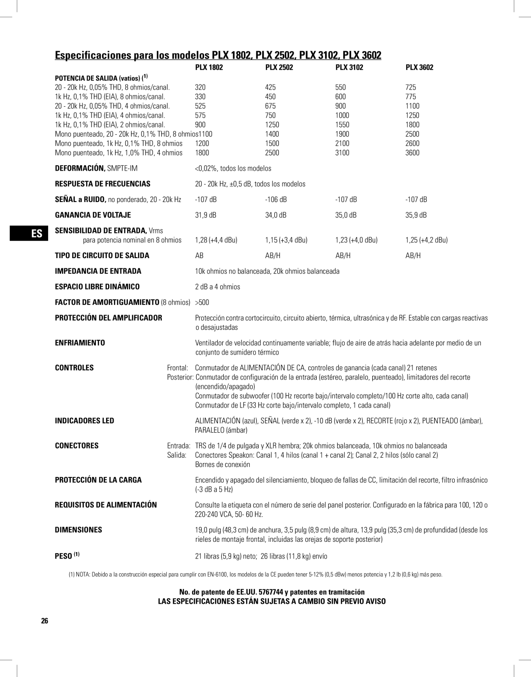
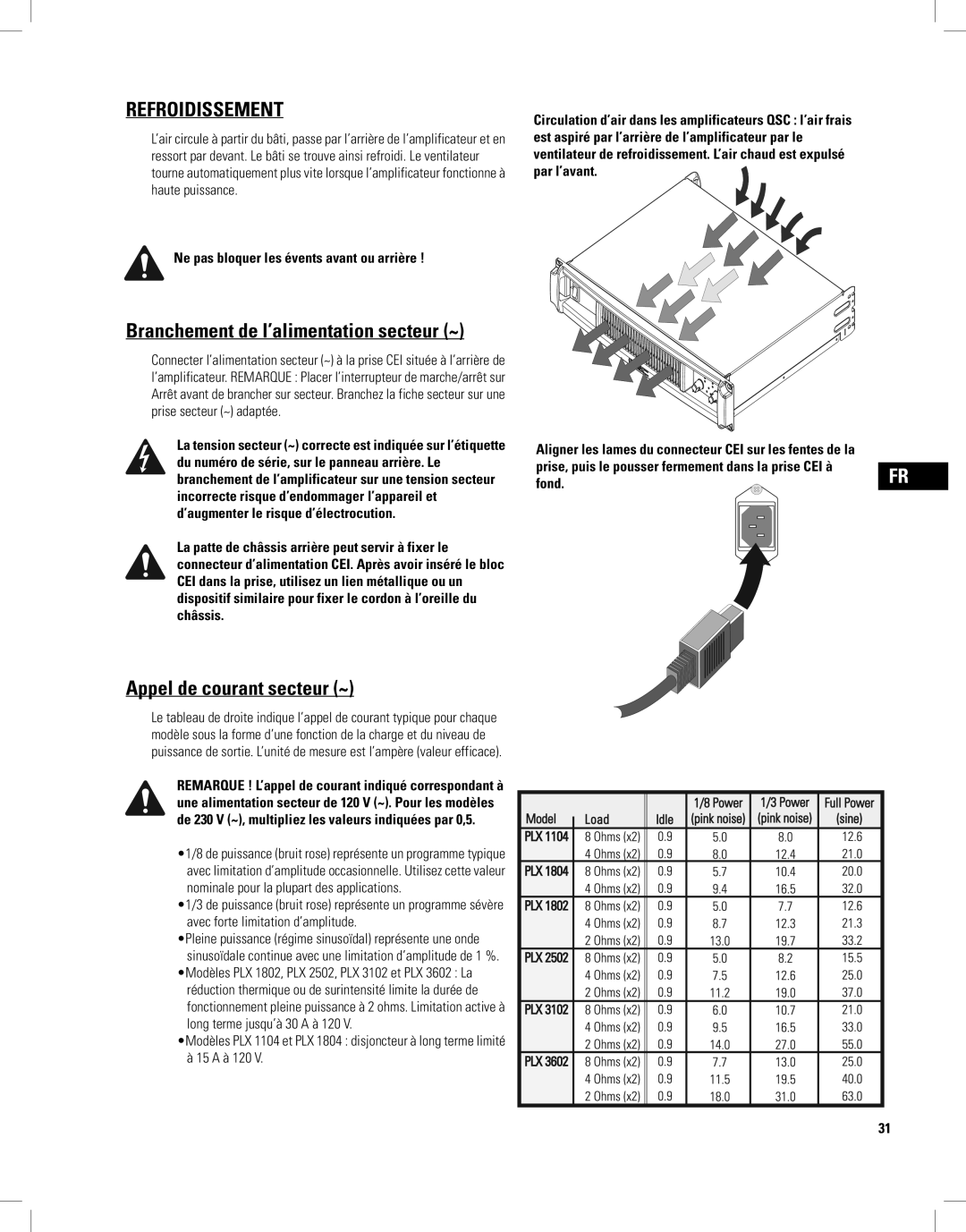
QSC Audio has long been recognized in the professional audio industry for its commitment to high-quality amplification solutions. The PLX series, which includes models such as PLX2502, PLX1804, PLX3602, PLX3102, and PLX1802, showcases the brand's innovative technologies and robust design philosophy, catering to a wide array of applications ranging from live sound to installation.The PLX2502 serves as a powerful amplifier capable of delivering 2,500 watts at 4 ohms. Its lightweight construction makes it easy to transport, while the efficient PowerLight™ technology helps reduce energy consumption without compromising performance. This model features dual independent channels, allowing for versatile operation and flexibility in wiring configurations.
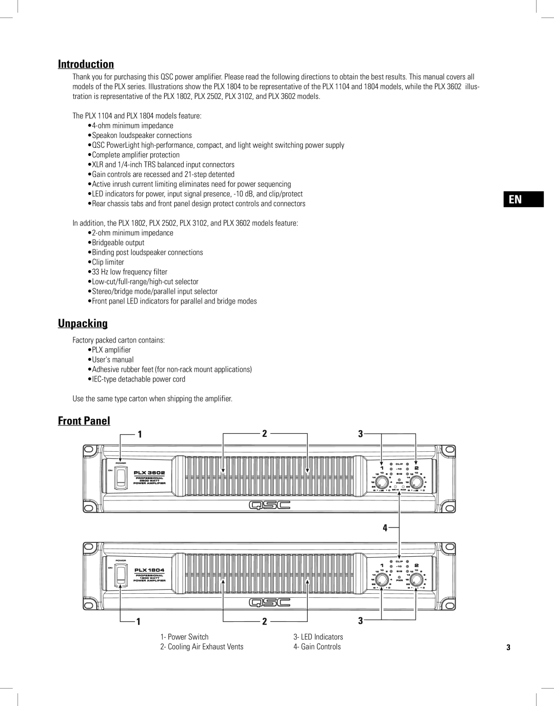
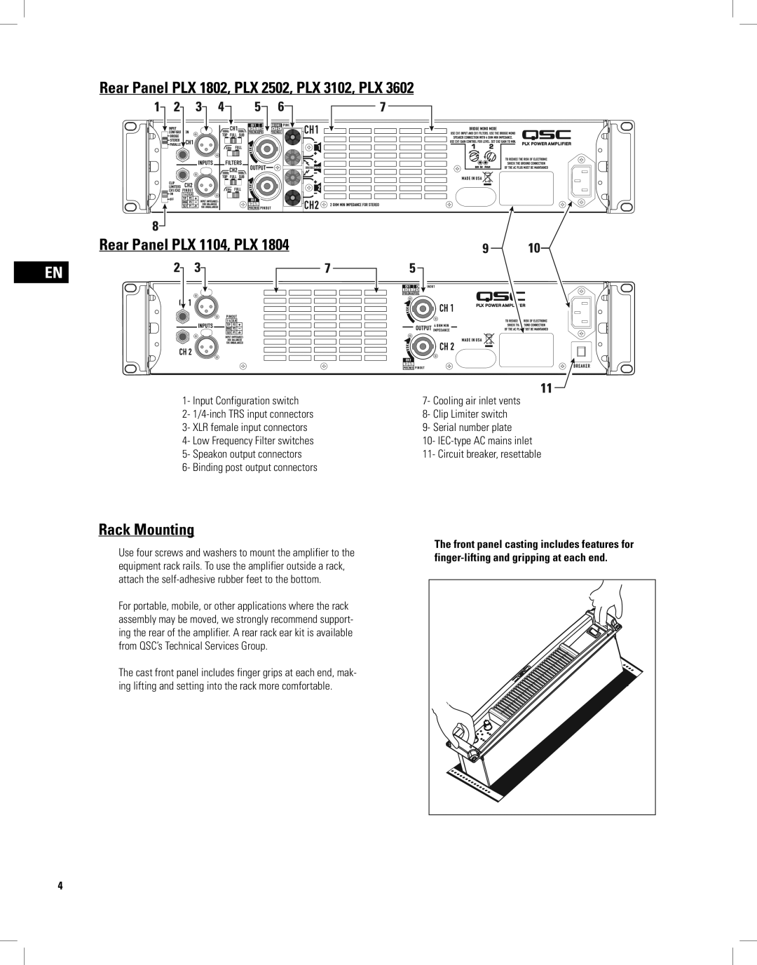
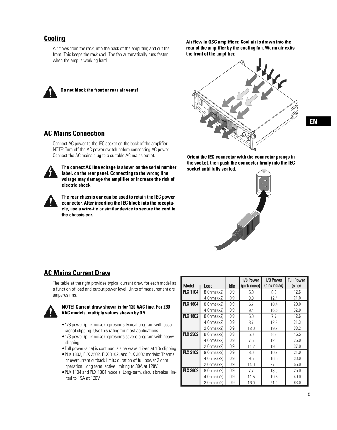
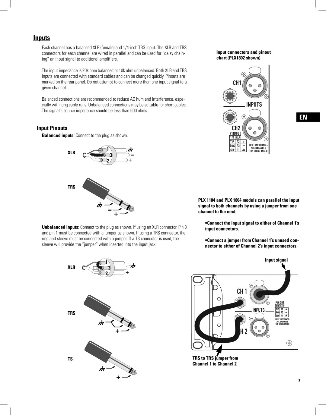
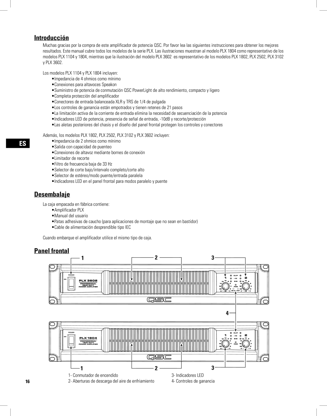
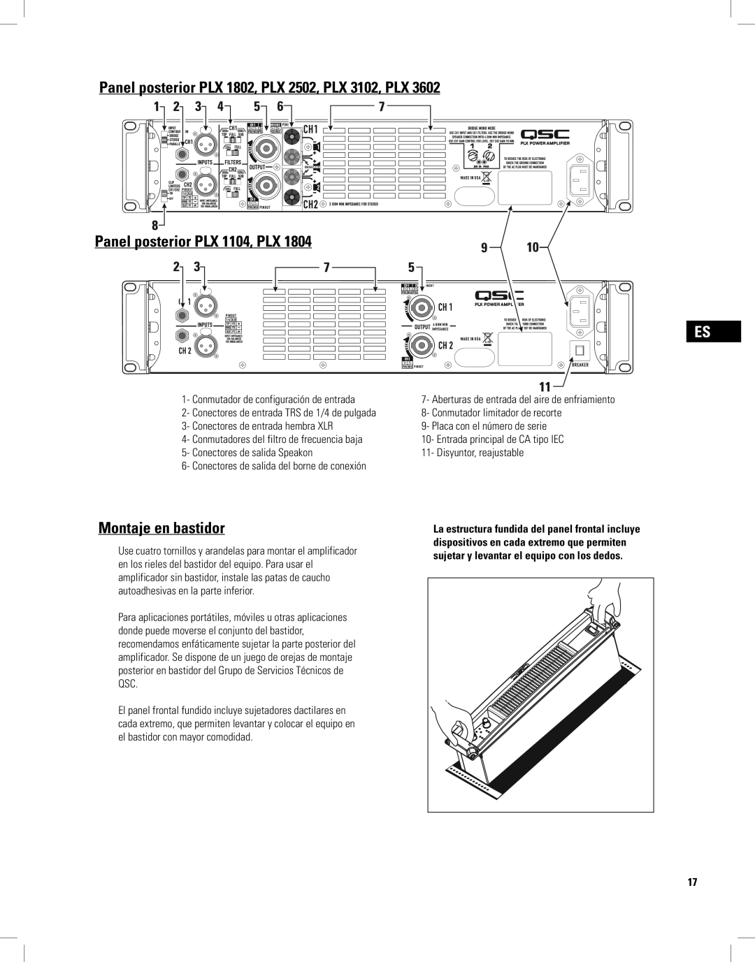
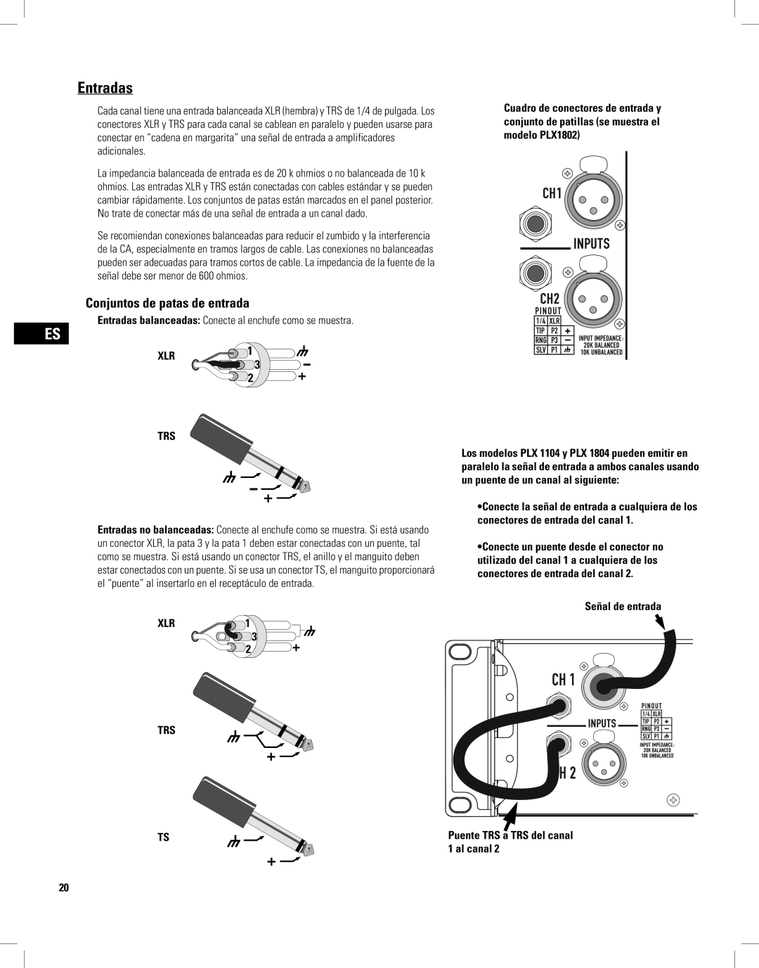
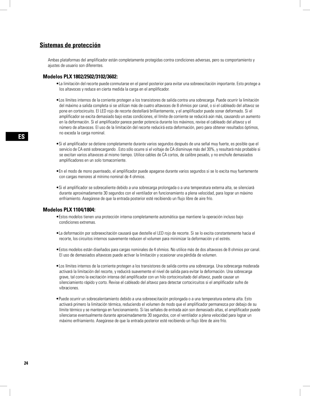
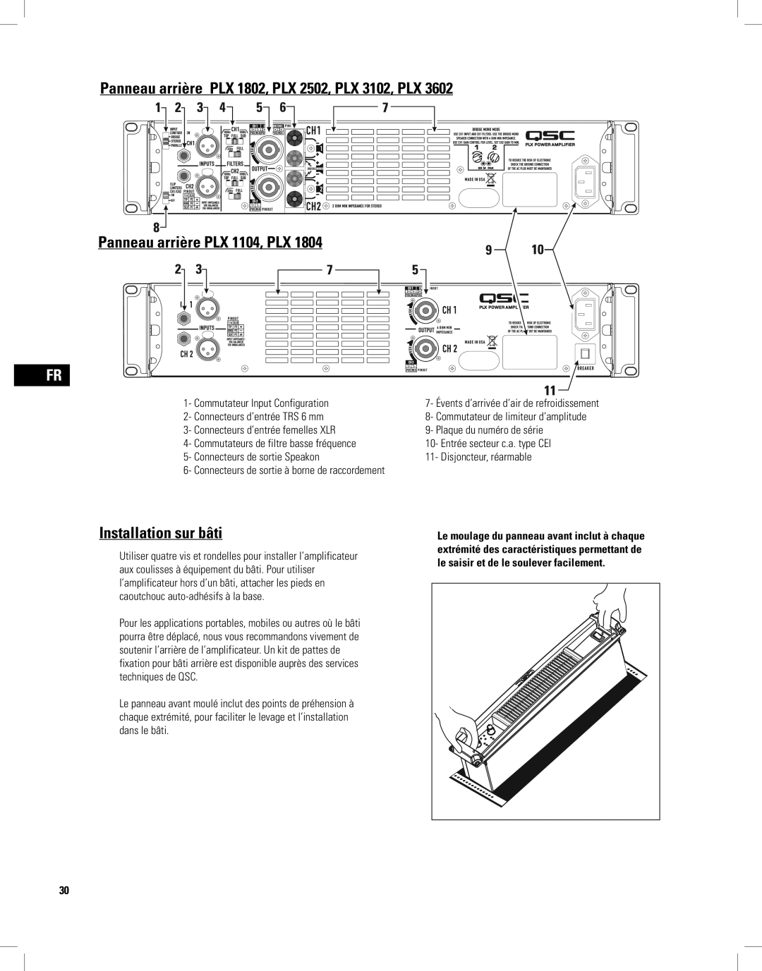
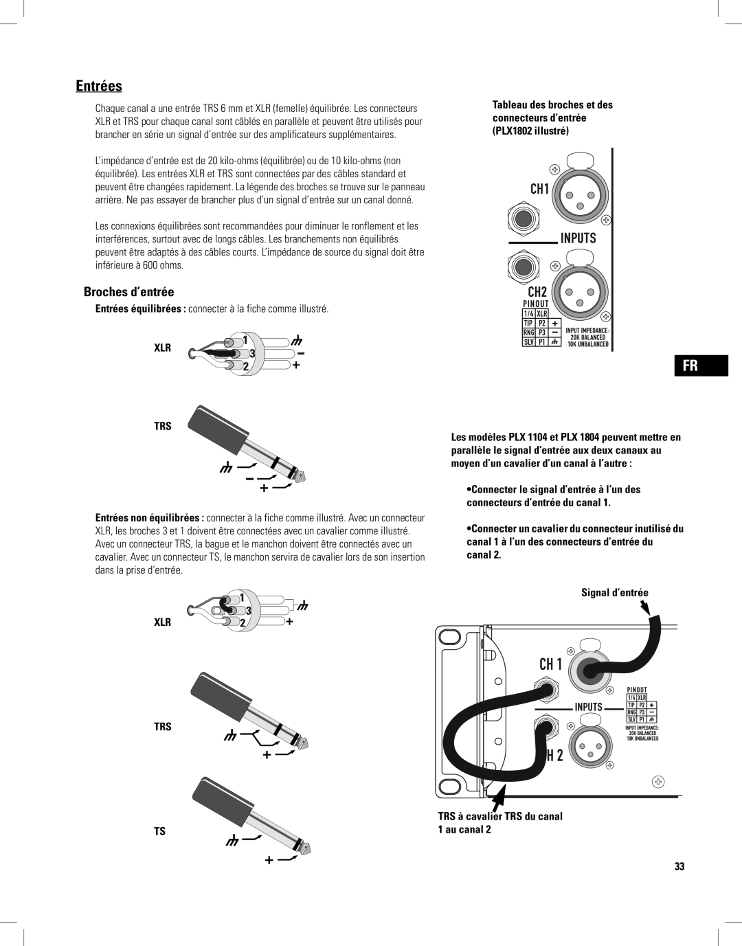
The PLX1804, on the other hand, offers slightly lower output while still delivering a solid 1,800 watts at 4 ohms. This model combines superior sound quality with a user-friendly interface. The specially designed fan cooling system ensures that the amplifier remains efficient even during demanding performance conditions. It also comes equipped with XLR and TRS inputs, providing compatibility with a wide range of audio sources.
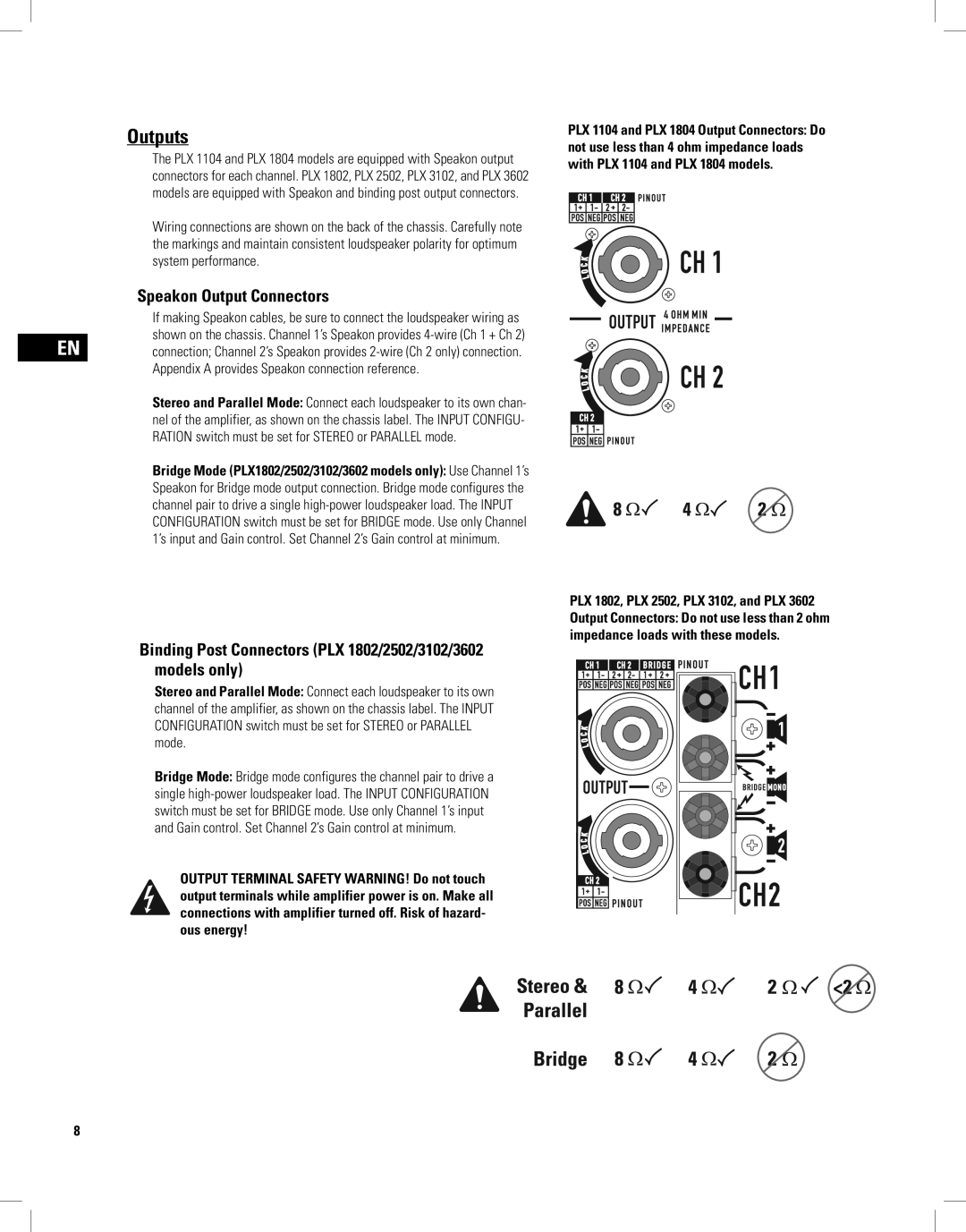
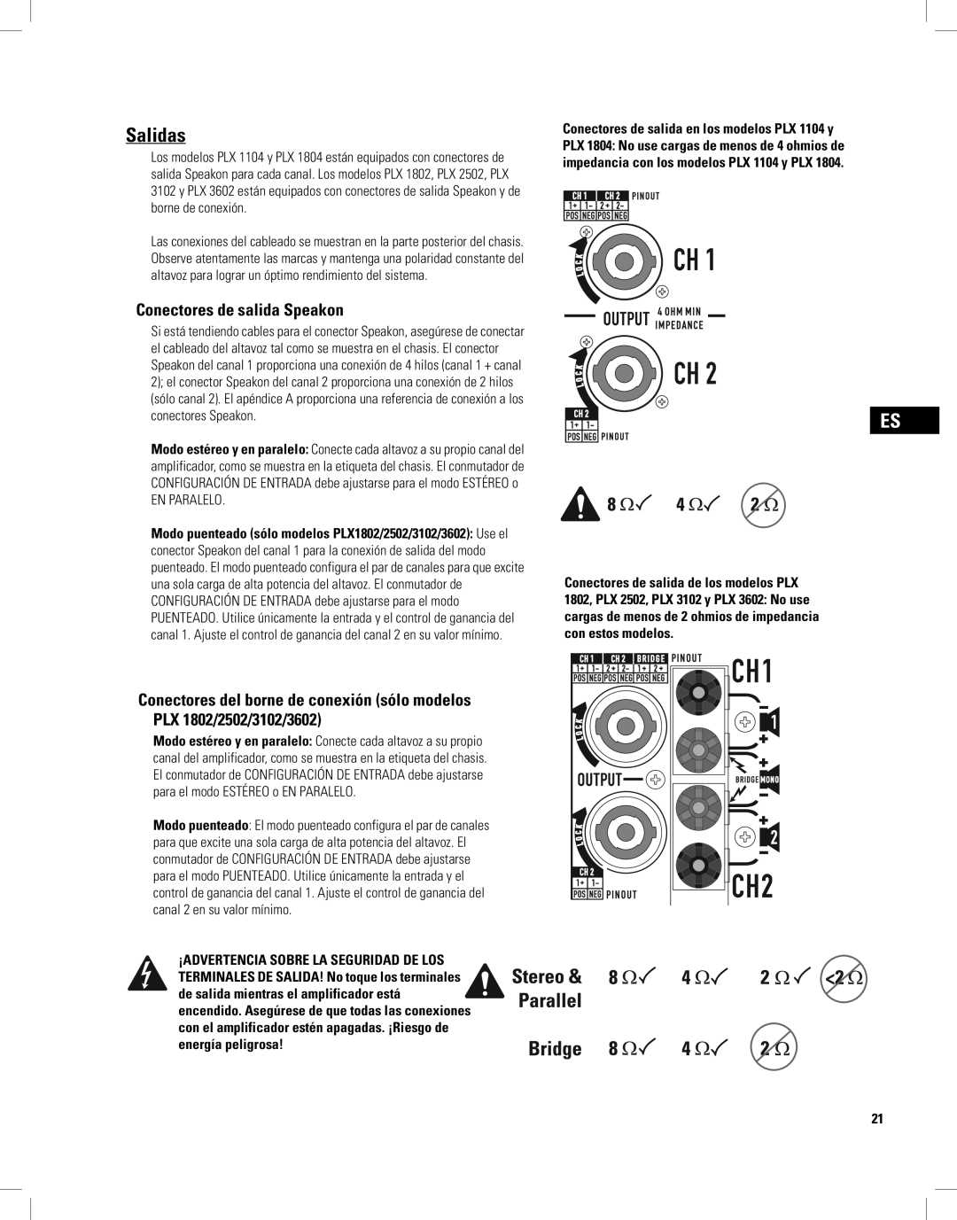
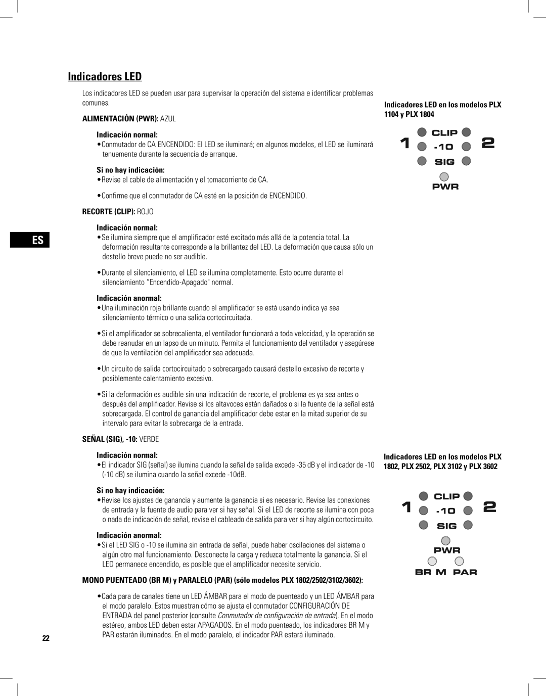
For those requiring even more power, the PLX3602 stands out with a massive 3,600 watts at 4 ohms. Its all-steel chassis enhances durability, making it suitable for rigorous touring environments. Additionally, the integrated DSP offers protection against overheating, short-circuits, and overloads. With its extensive range of outputs, the PLX3602 supports complex setups involving multiple speakers and driving high-demand audio systems.
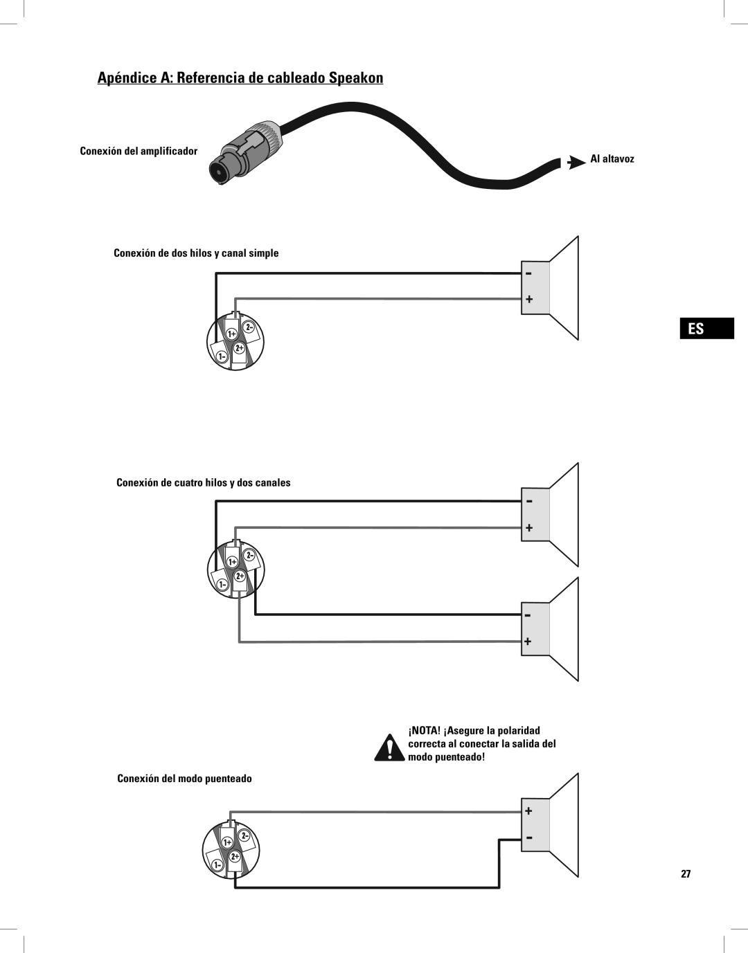
The PLX3102 is another noteworthy model in the series, providing an output of 3,100 watts. This amplifier emphasizes versatility and can drive various speaker configurations efficiently. It features both binding post and Speakon outputs, ensuring secure and reliable connections, even in high-stress scenarios.
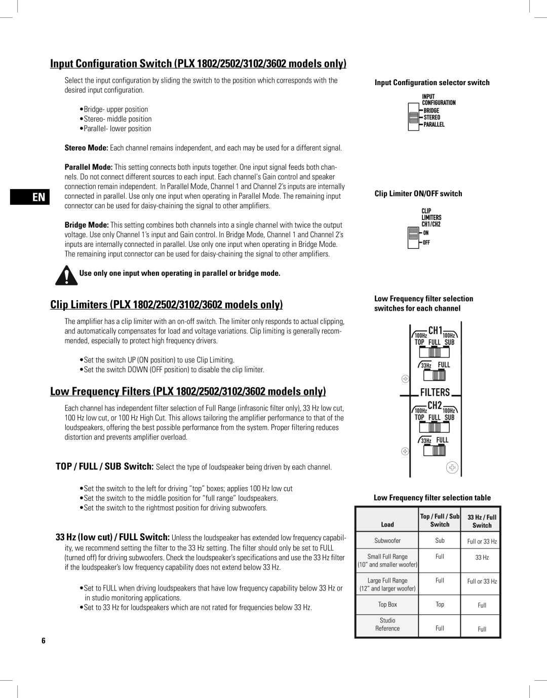
Lastly, the PLX1802 rounds out the series with 1,800 watts of power. Known for its compact size, it is particularly suited for smaller venues or as a monitor amplifier. Despite its smaller footprint, the PLX1802 retains the robust performance characteristics that QSC is known for.
Overall, the PLX series epitomizes QSC’s dedication to quality audio amplification, combining power, portability, and advanced features across an impressive range of models. With their advanced technologies, including PowerLight™ and integrated DSP, these amplifiers are designed to meet the rigorous demands of both live and installed sound applications while delivering exceptional sound quality.
