Yamakawa M2150 manual ISO Connector, Connector a, Auto Antenna Output +12V to Ignition KEY Ground

Page 9

Installation

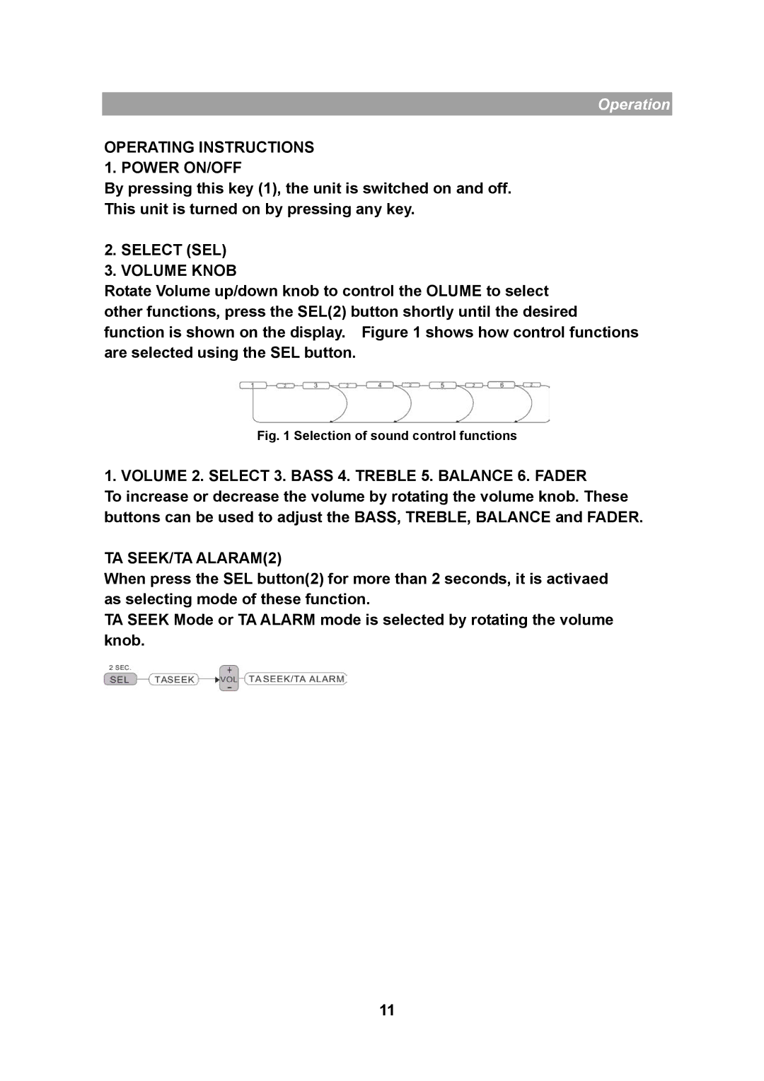
ISO CONNECTOR

RCA Jack Line Out(Rear)-Gray

:Red (right)

:White (left)

CONNECTOR A 1.

2.

3.

4.MEMORY +12V

5.AUTO ANTENNA OUTPUT

7.+12V (TO IGNITION KEY)

8.GROUND

The connector A no.7 must be connected by car ignition key in order to avoid that car battery becomes weak when the car

will be not used for long period.

CONNECTOR B

1.REAR RIGHT SPEAKER (+)

2.REAR RIGHT SPEAKER (-)

3.FRONT RIGHT SPEAKER (+)

4.FRONT RIGHT SPEAKER (-)

5.FRONT LEFT SPEAKER (+)

6.FRONT LEFT SPEAKER (-)

7.REAR LEFT SPEAKER (+)

8.REAR LEFT SPEAKER (-)

9

Image 9
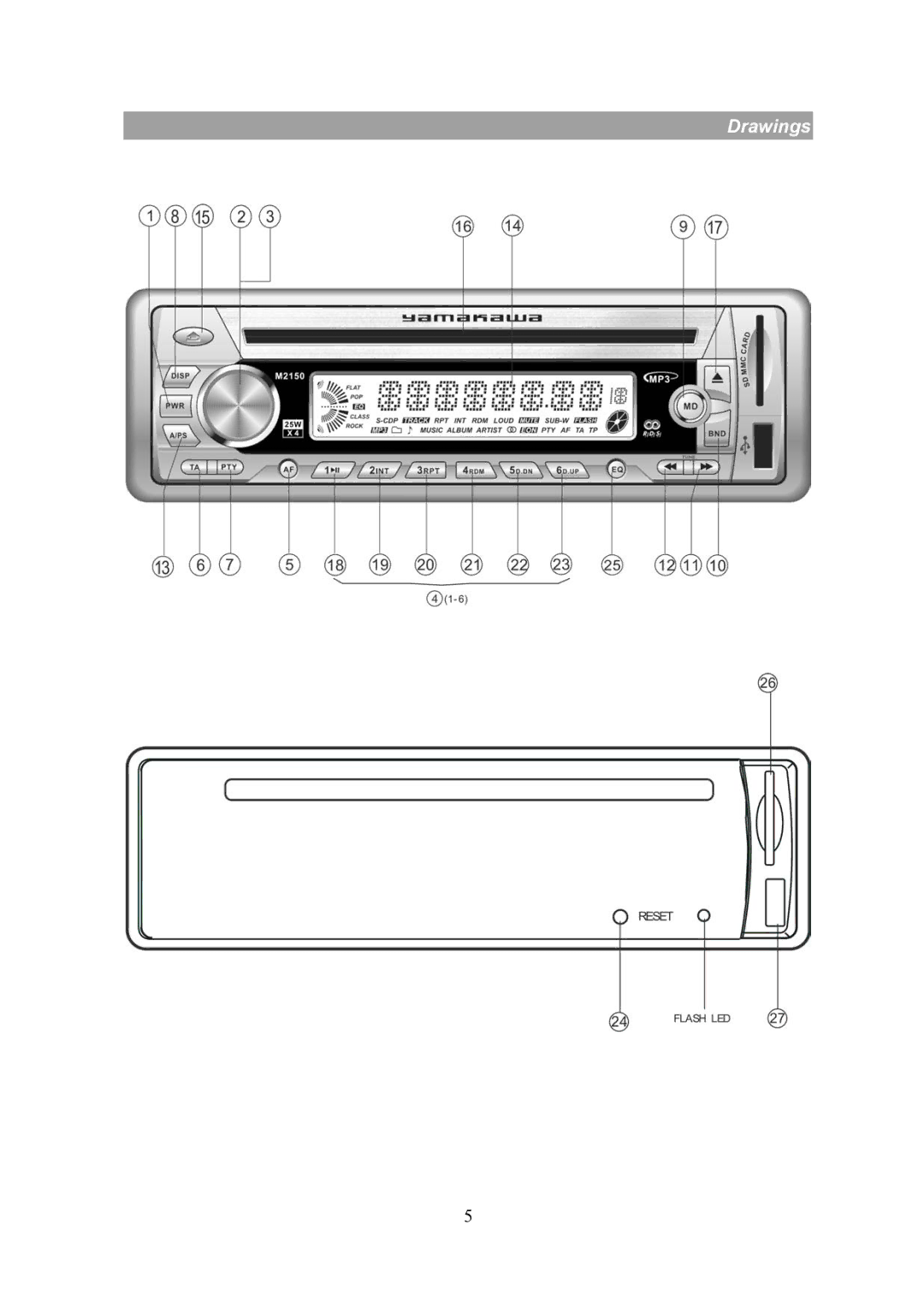
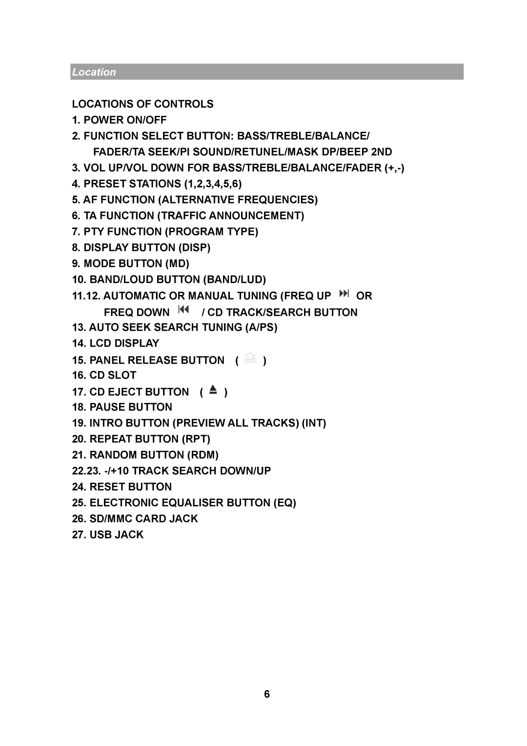
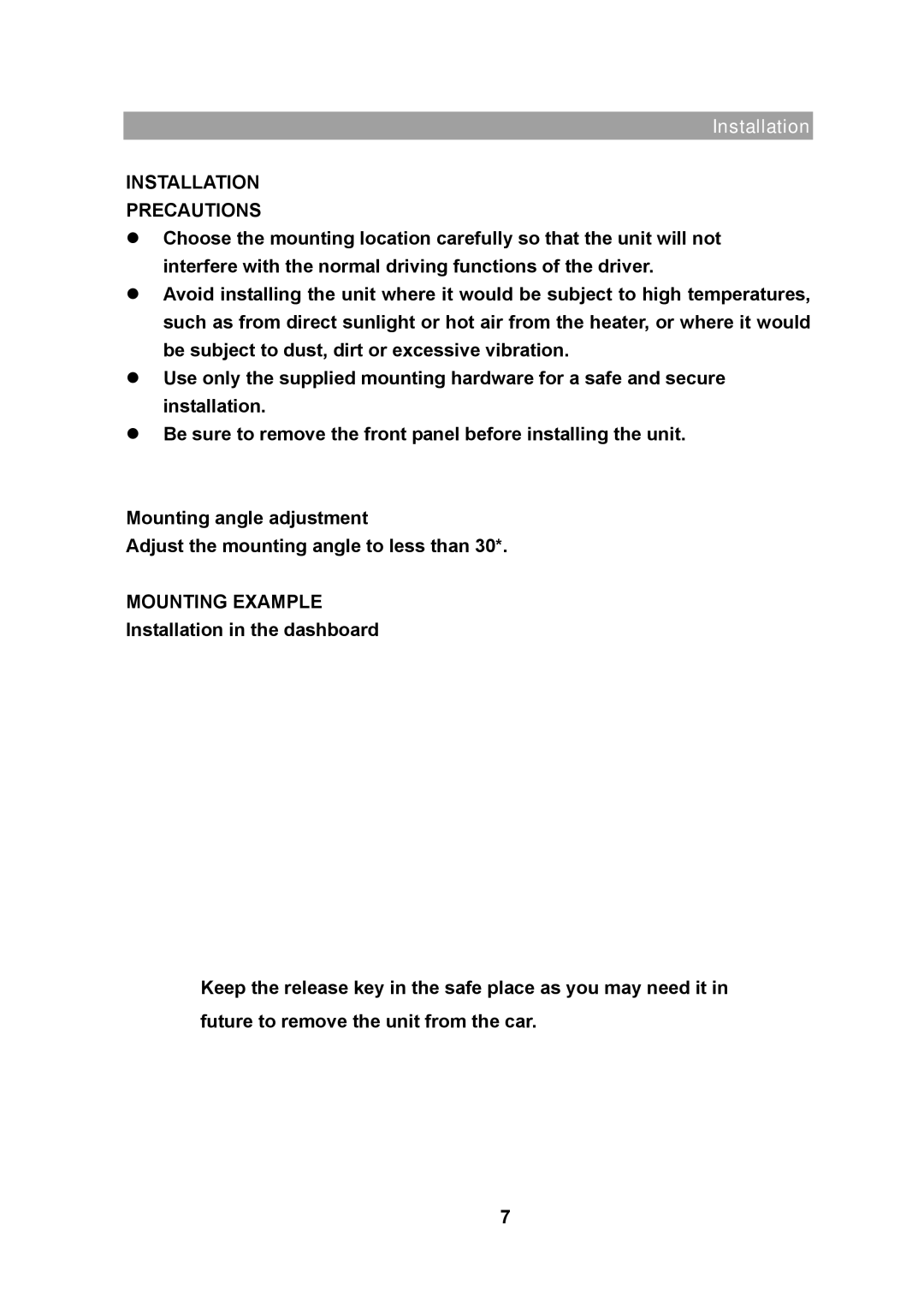
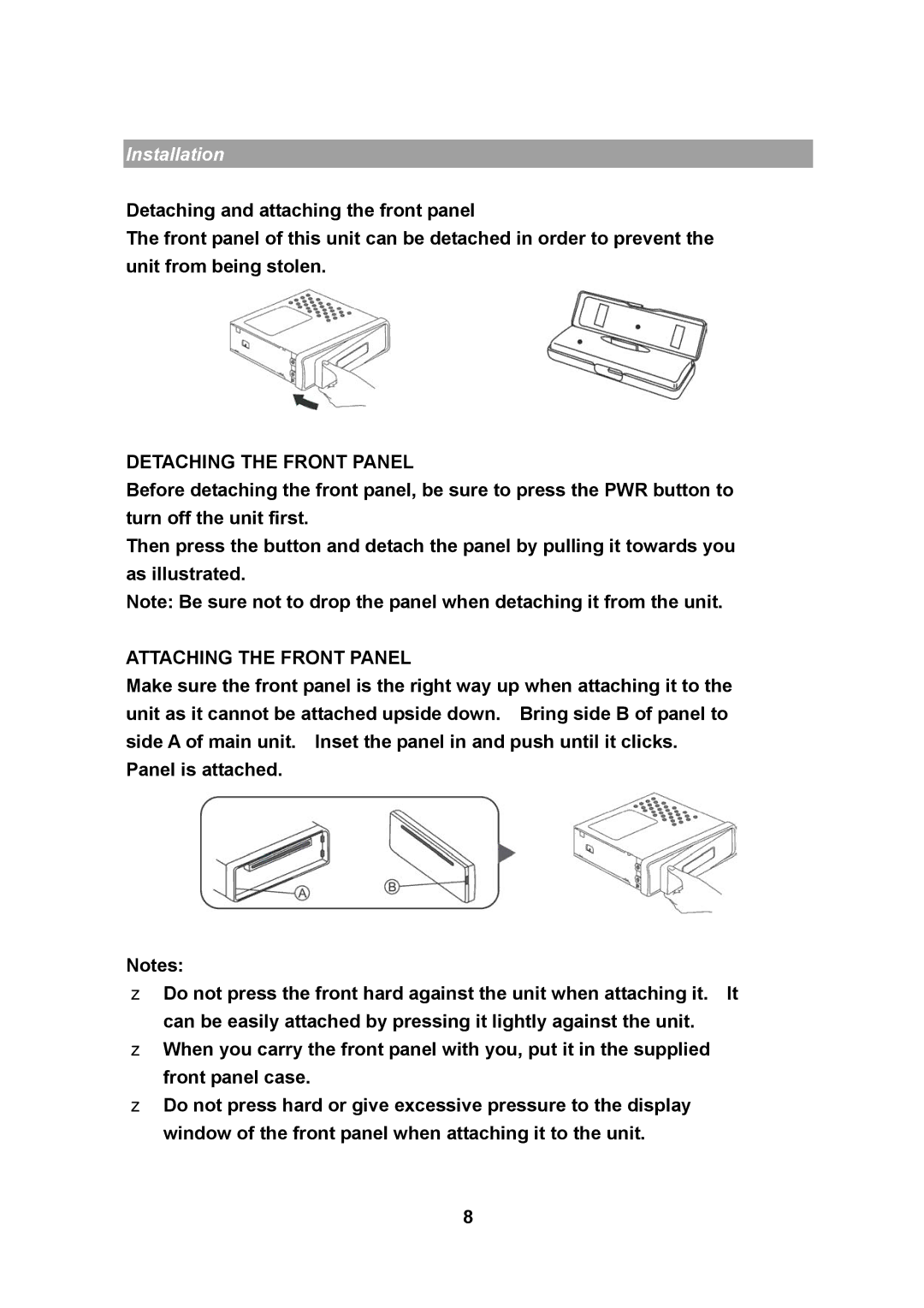
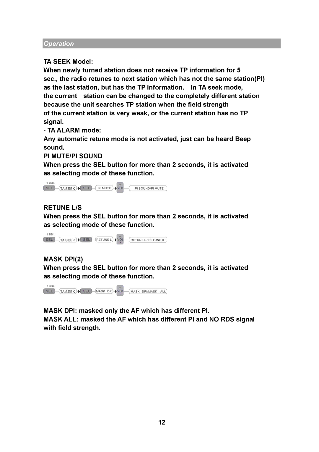
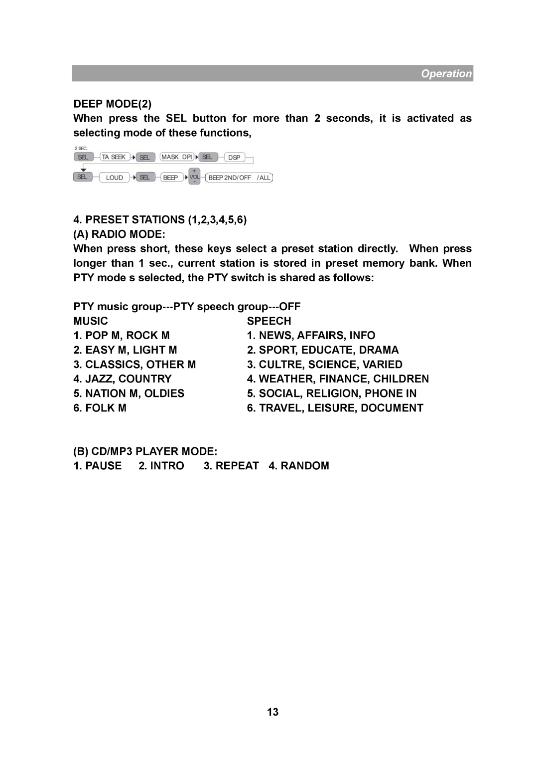
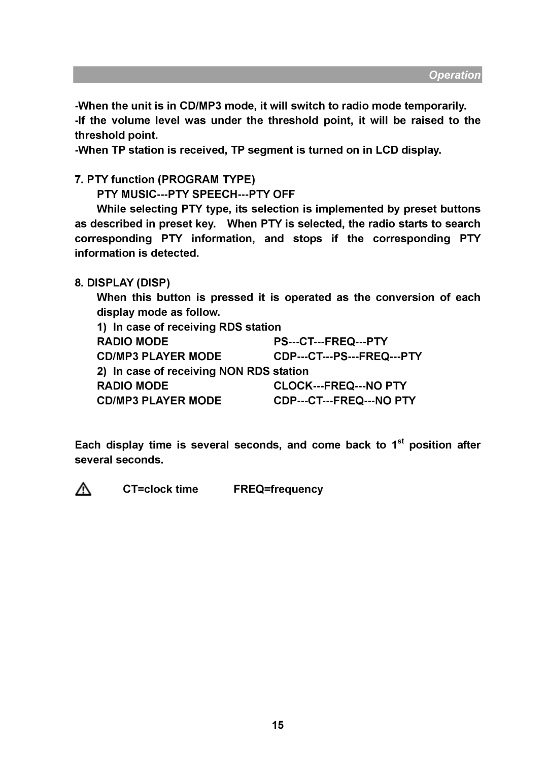
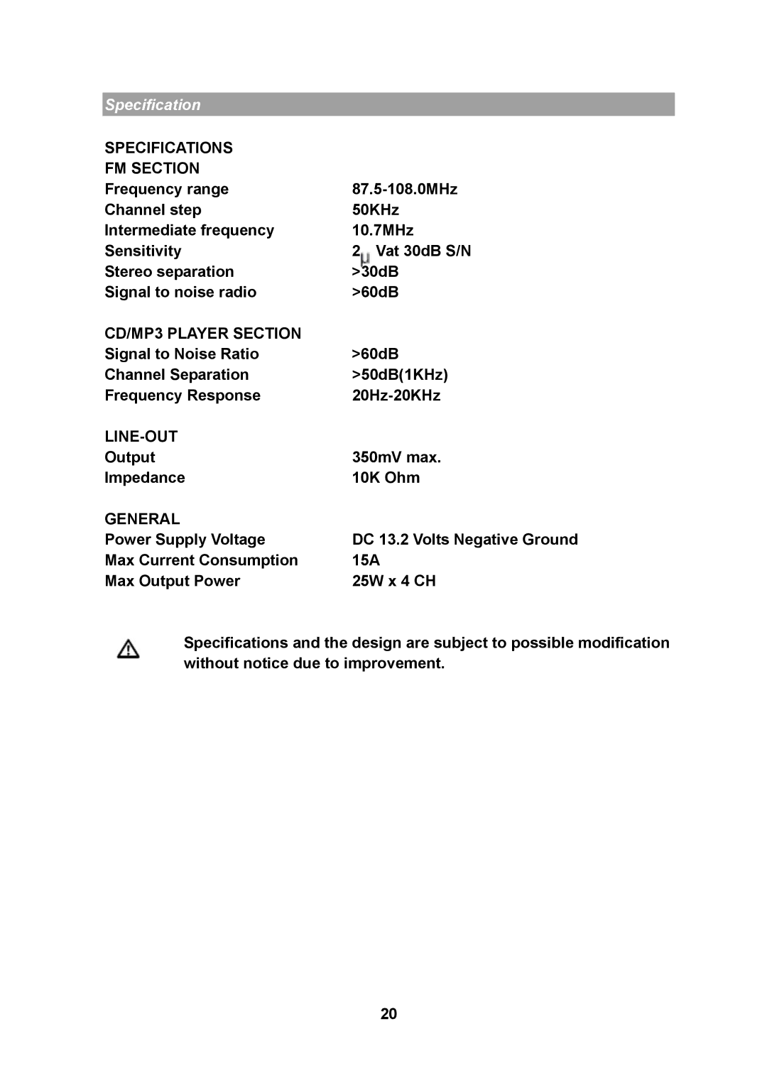
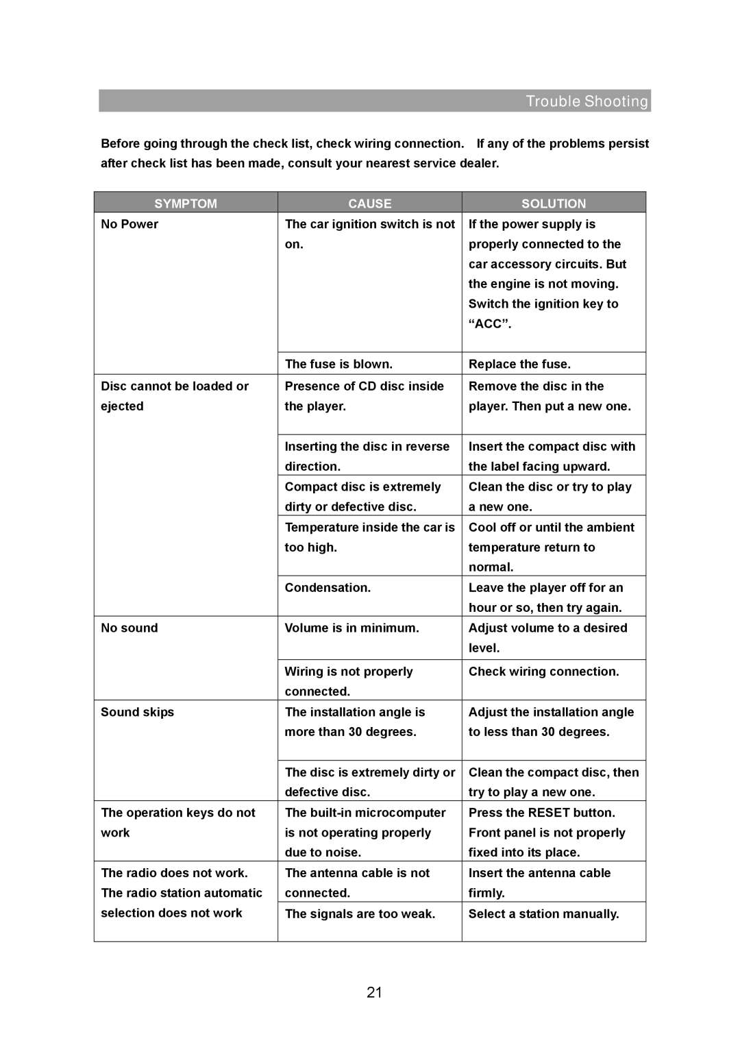
Contents Model M2150 Function FeaturesContent Page Drawings Locations of Controls Power ON/OFF LocationVOL UP/VOL Down for BASS/TREBLE/BALANCE/FADER + Installation Installation PrecautionsMounting Example Attaching the Front Panel Detaching the Front PanelISO Connector Connector aAuto Antenna Output +12V to Ignition KEY Ground Fuse Replacement Select SEL Volume Knob Operating Instructions 1. Power ON/OFFVolume 2. Select 3. Bass 4. Treble 5. Balance 6. Fader OperationPI MUTE/PI Sound Retune L/SMask DPI2 Deep MODE2 Radio ModeOperation Display Disp PTY MUSIC---PTY SPEECH---PTY OFFBand / LUD Button BND/LUD Automatic or Manual Tuning Freq UP or FreqTUN …REVERSE CD Control Location of Parts Skip TRACK/SEARCH ButtonCD Slot CD Eject Button Track DOWN/UP SelectTrack Down 6 10 Track UP Reset HOW to Select MP3 FilesINT Track DownSpecifications FM Section SpecificationCD/MP3 Player Section LINE-OUTSymptom Cause Solution Trouble Shooting