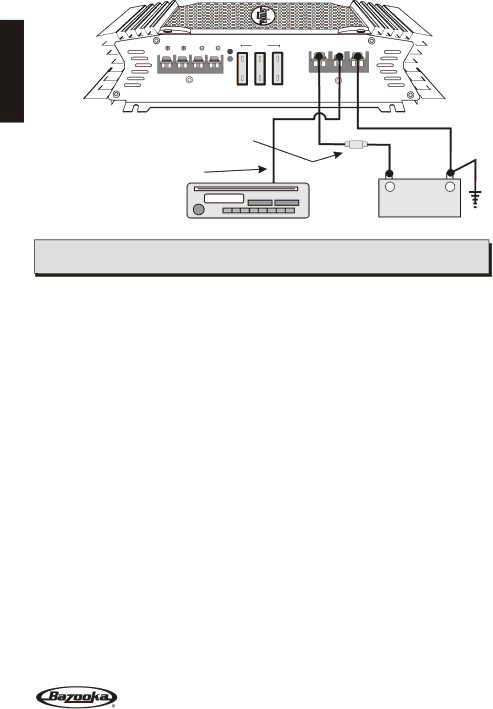
Bazooka ELA1300, ELA2100, ELA2150 Power Connections, Connect the amplifier to the cars battery

Page 8

POWER CONNECTIONS

ENGLISH

SP

SP

SP

SP

PROTECT

25A

FUSES

25A


25A

POWER

SPEAKERS

IN-LINE POWER FUSE

MOUNTED WITHIN 12"

FROM BATTERY RECOMMENDED

(NOT PROVIDED)

RADIO'S REMOTE

TURN-ON OUTPUT

94.7

+12V REM GND

+-

CAR BATTERY

+12V

IMPORTANT! Before making any connections, disconnect the car’s battery until the installation is completed to avoid possible damage to the electrical system.

Connect the amplifier to the car's battery.

At times, the amplifier will need to draw large levels of current that cannot be provided by any circuit in the car's fuse box. We recommended using an 4 to 8 gauge power wire for your connections depending on the amplifier and length of the wire. Strip one end of the wire to crimp on a barrier spade. Loosen the +12V screw terminal and insert the power wire with the barrier spade and tighten. Use caution to make sure no stray wire stands come in contact with surrounding terminals causing short circuits. Run the wire directly to the positive terminal of the car's battery. Make sure to use an in-line fuse within 12” of the car's battery to protect the electrical system and amplifier against short circuits and/or power surges.

Connect the ground terminal of the amplifier to the car's chassis.

For the ground connection, use an 4 to 8 gauge wire (black) to connect to the terminal marked GND and then connect it to the car's chassis. Try to keep the length of the cable as short as possible, preferably less than 6". Also make sure that the point on the car where the connection is to be made is free of paint and dirt.

Connect the remote terminal of the amplifier to a switchable +12V source.

This connection allows the amplifier to be turned on and off with the power control of the radio. If the radio has a REMOTE output terminal, connect it to the amplifier's terminal marked REMOTE (using a 16 gauge wire or heavier). Now when the radio is turned on, the amplifier will automatically turn on. This connection can also be made to the radio’s Power Antenna wire.

7

Image 8
Contents Page English ELA Amplifiers Safety Precautions Features and Benefits Phase Adjustment ELA1190, ELA1300, ELA1500 & ELA1800 Power FusingAdjustable Input Sensitivity Subsonic Filter ELA1190, ELA1300, ELA1500 & ELA1800Mounting Location Power Connections Connect the amplifier to the cars batterySignal Connections Signal ConnectionsHigh Level Connections Optional 94.7ELA465 Connections Common Ground Radio Speaker Connections Speaker Connections Bridged Speaker Connections TRI-MODE Remote Bass Control Module Optional Adjusting the X-OVER and Bass Fine Tune the SystemTrouble Shooting the System Look for SolutionSpecifications ELA265 ELA465 ELA2100Limited Warranty How to obtain warranty services Français Mesures DE Sécurité Utilisez des connecteurs de fil de catégorie supérieureNe faites pas passer de câbles sous le véhicule Soyez prudent lors du montage de lamplificateurFonctions ET Avantages Ajustement de la phase ELA1190, ELA1300, ELA1500 et ELA1800 Filtre subsonique ELA1190, ELA1300, ELA1500 et ELA1800Fusibles de ligne Mise en route à distanceEmplacement DE Montage Raccords Dalimentation Connectez lamplificateur à la batterie du véhiculeRaccordement DES Transmissions Connexions SignalConnexions Signal ELA465 Connexions DE Niveau Élévé Optionnelles Connexions À Deux Canaux Radio À Masse CommuneConnexions ELA465 Radio À Masse Commune Connexions DES HAUT-PARLEURS ELA465 Raccordements DES HAUT-PARLEURSConnexions DES HAUT-PARLEURS ELA265, ELA2100 ET ELA2150 Connexions DES HAUT-PARLEURS EN Dérivation Connexions DES HAUT-PARLEURS EN Dérivation ELA465Connexions DES HAUT-PARLEURS Trois Modes Module DE Commande DES Basses À Distance Réglage DU Filtre Passif ET DES Basses Dépannage DU Système RechercheSpécifications ELA265 ELA465 ELA2100Garantie Limitée Comment obtenir des services de garantie Español Fusible principal Utilice terminales para cable adecuadasNunca pase los cables por debajo del vehículo Tome precauciones cuando instale el amplificadorCaracteristicas Y Beneficios Filtro subsónico. ELA1190, ELA1300, ELA1500 y ELA1800 Ajuste de fase . ELA1190, ELA1300, ELA1500 y ELA1800Fusible RemotoUbicacion DEL Amplificador Conexion DE LA Alimentacion Conexión del amplificador a la bateríaELA465 Conexiones DE Señal Entradas DE Baja SeñalConexiones DE Señal Entradas DE Alta Señal Opcional Radio DE 4 Canales CON Tierra Flotante CON ELA465 Radio DE 4 Canales CON Tierra Comun CON ELA465Salida DE Bocinas Conexion DE Bocinas ELA465Conexion DE Bocinas EN Puente ELA465 Conexion Tipo Puente BridgedConexion DE Bocinas EN Puente ELA265, ELA2100 Y ELA2150 Conexion TRI-MODO 100Control Remoto DE Bajos Opcional Ajuste Fino DEL Sistema Ajuste fino de la sensibilidad de entrada del amplificadorSolucion ProblemaFallas Tipicas DEL Sistema Especificaciones ELA1500 ELA2150 ELA1800Condiciones DE Garantia Cómo obtener el servicio de garantía Español Español Español