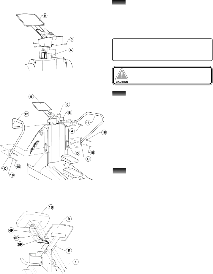
1Position the Monocolumn assembly (#9) above ![]() the CHANNEL FRAME bracket (A) located at the top of the
the CHANNEL FRAME bracket (A) located at the top of the
NOTE: Be sure to feed all cables leading from the channel frame bracket up and through the monocol- umn assembly before mounting the monocolumn assembly to the channel frame bracket.
Be careful not to pitch any of the cables between the monocolumn assembly and the channel frame bracket.
2Remove the four HANDRAIL MOUNTING ![]() BOLTS (#15) with WASHERS (#16) FROM THE HANDRAIL MOUNTING BRACKET (D). Slide the user- right HANDRAIL (#11) over the HANDRAIL MOUNTING POST (B) as shown until the HANDRAIL MOUNTING PLATE (C) is aligned with the HANDRAIL MOUNTING BRACKET (D) located on the back face of the unit body. With two BOLTS (#15) with WASHERS (#16), attach the
BOLTS (#15) with WASHERS (#16) FROM THE HANDRAIL MOUNTING BRACKET (D). Slide the user- right HANDRAIL (#11) over the HANDRAIL MOUNTING POST (B) as shown until the HANDRAIL MOUNTING PLATE (C) is aligned with the HANDRAIL MOUNTING BRACKET (D) located on the back face of the unit body. With two BOLTS (#15) with WASHERS (#16), attach the
Repeat this step to install the user left HANDRAIL (#12).
3Locate the ![]() from the MONOCOLUMN assembly (#9) and con- nect it to the
from the MONOCOLUMN assembly (#9) and con- nect it to the
Locate the
Locate the
Place the DISPLAY CONSOLE (#10) on the Display Console Bracket (E), insert the four DISPLAY CONSOLE SCREWS (#1) and tighten in a