GE manual Gas Turbine Operability, Large Operability Window

Page 20

Gas Turbine Operability

Large Operability Window

GE Energy offers a variety of innovative design solutions to maximize the operability window of the Oil & Gas gas turbine fleet. In addition to variable stator vanes and blow-off valves, the design solutions include:

-variable turbine nozzle guide vanes

-a variable bypass combustion chamber

-a high turn-down capability combustion chamber

-CPC optimizing control logic

The various combinations of design solutions are specifically adapted to the demands of the marketplace for each gas turbine model.

For example: The GE10-2 DLN (Dry Low NOx) model utilizes a variable bypass combustion chamber to maintain the optimum flame temperature for low emissions all the way down to 50% load, and the variable nozzle guide vanes of the free power turbine to ensure that the gas generator shaft speed is always at the design value, thereby ensuring maximum output.

The MS5002D instead uses variable nozzle guide vanes to maintain maximum output on the standard model, and maintain the optimum flame temperature for low emissions down to 50% load on the DLN model. They are also used in regenerative cycle applications to maximize the efficiency of the regenerator and hence to maximize fuel economy.

The brand new MS5002E makes use of the DLN2 combustion design used in GE’s F-Class machines to ensure low emissions over a range of flame temperatures, thereby delaying the opening of the blow-off valves at part load while maintaining the highest possible efficiency at base-load.

Note that the flexibility given by each of these solutions gives a further performance advantage on cold days with respect to other engines that are forced to open
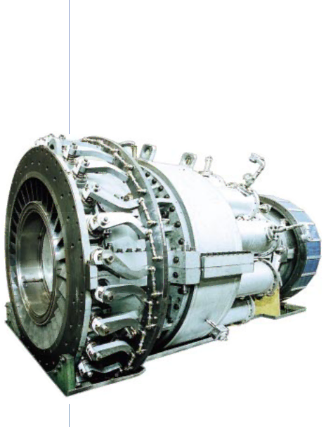
 blow-off valves (to meet environmental emissions laws) even at base-load.

MS5002D Gas Turbine

20 GE Energy Gas Turbines

Image 20
Contents Gas Turbines Contents GE Energy Gas Turbines Turbine GE5 Gas TurbinesCompressor Combustor Package Maintenance Philosophy Some KEY PointsGE10 Gas Turbines Generator Drive Single Shaft VersionAuxiliaries Mechanical Drive Two Shaft VersionMS5001 Gas Turbines MS5002C-DGas Turbines MS5002E Gas Turbines MS6001B/MS7001EA/MS9001E General Specifications PGT16 Aeroderivative Gas TurbinesPGT25 Aeroderivative Gas Turbines GAS GeneratorPGT25+ Aeroderivative Gas Turbines LM6000 Aeroderivative Gas Turbines Main Components Axial CompressorFirst Stage Nozzle Buckets and WheelsGas Turbine Operability Large Operability WindowAmbient Temperature 22 C CPC LogicLNG Exploration and Production, Floating Production Units Gas, Water Injection & Gas Storage UnitsPipeline Pipeline Standard Units/PackagesRefinery and Petrochemicals Downstream PlantsTest Facilities Service Training Solutions TrainingCenter of Excellence for Training Covered EquipmentISO Rated Heat Rate Effic Mechanical Drive ISO conditions natural gas shaft output Generator Drive Mechanical Drive GE imagination at work