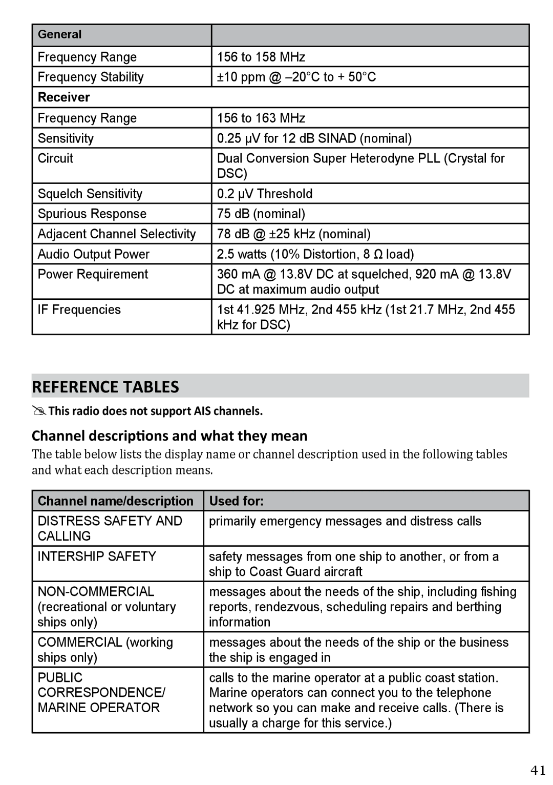
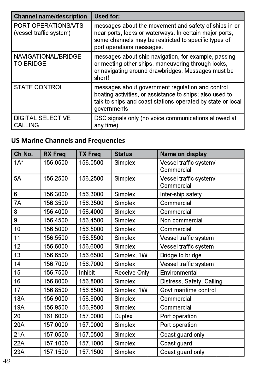
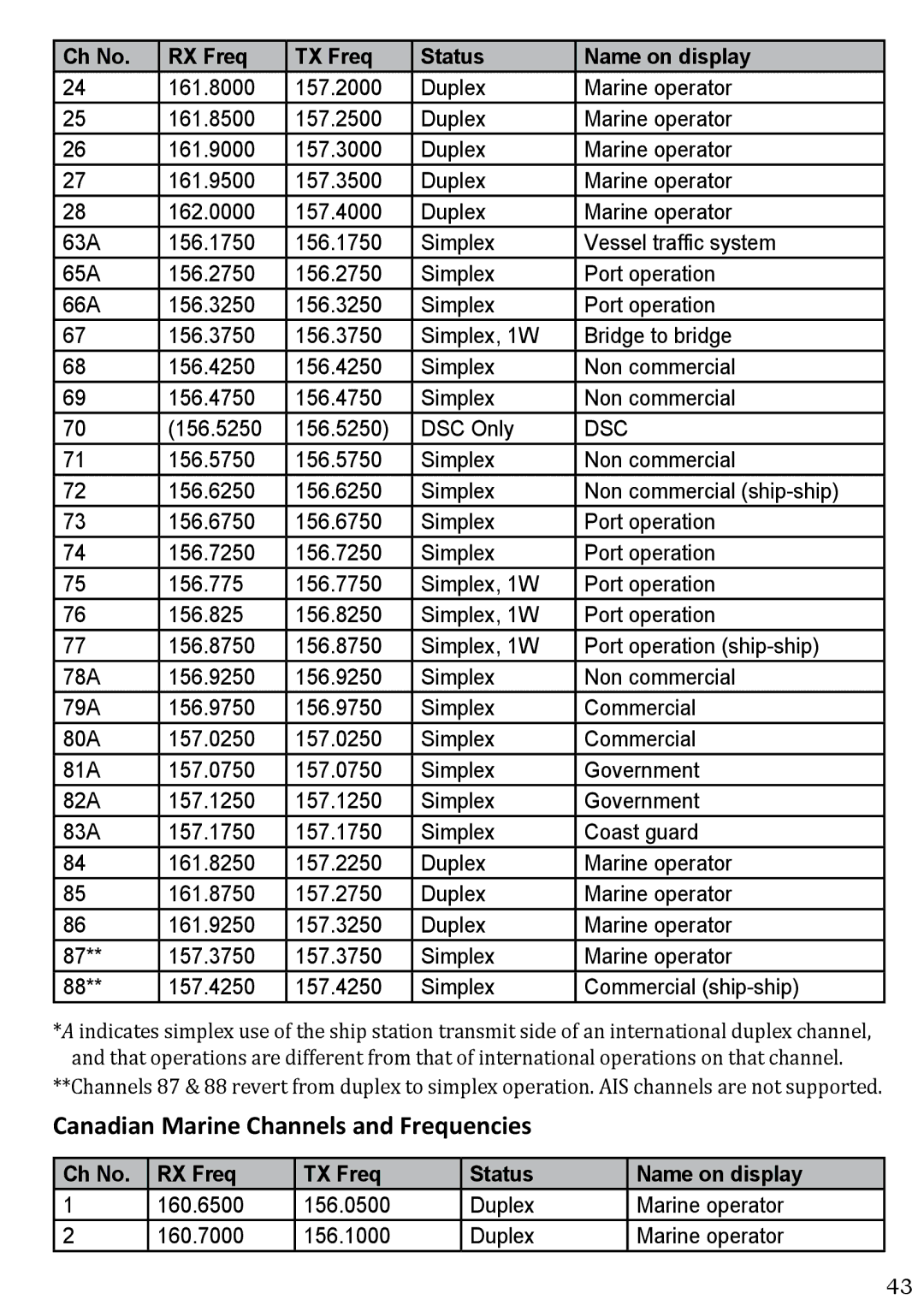
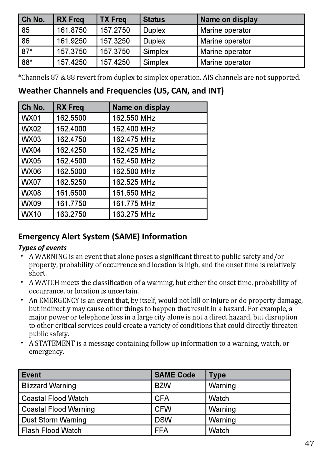
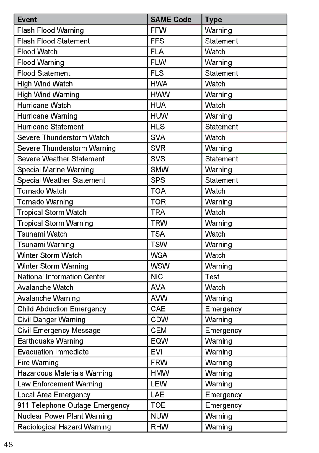
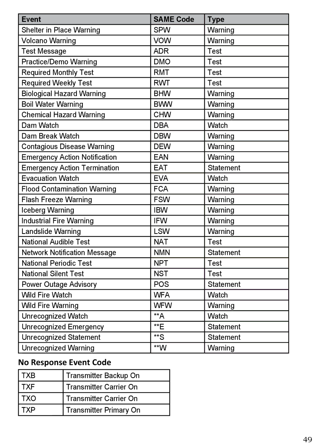
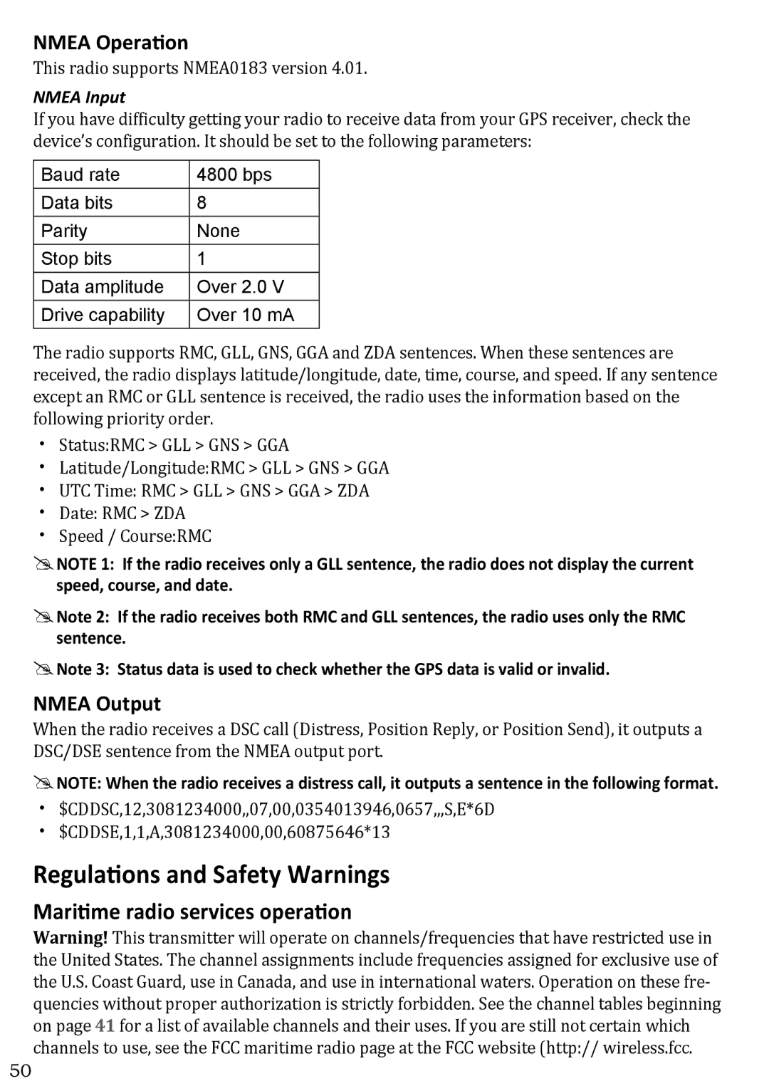
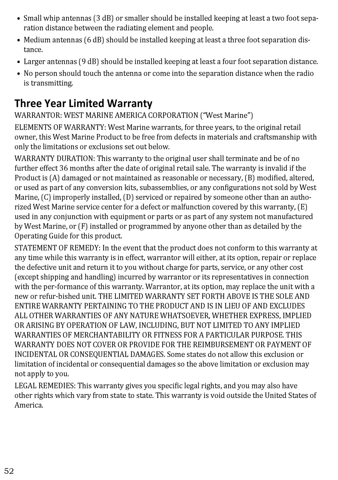
West Marine VHF580 manual GPS Data External, Configuring the GPS

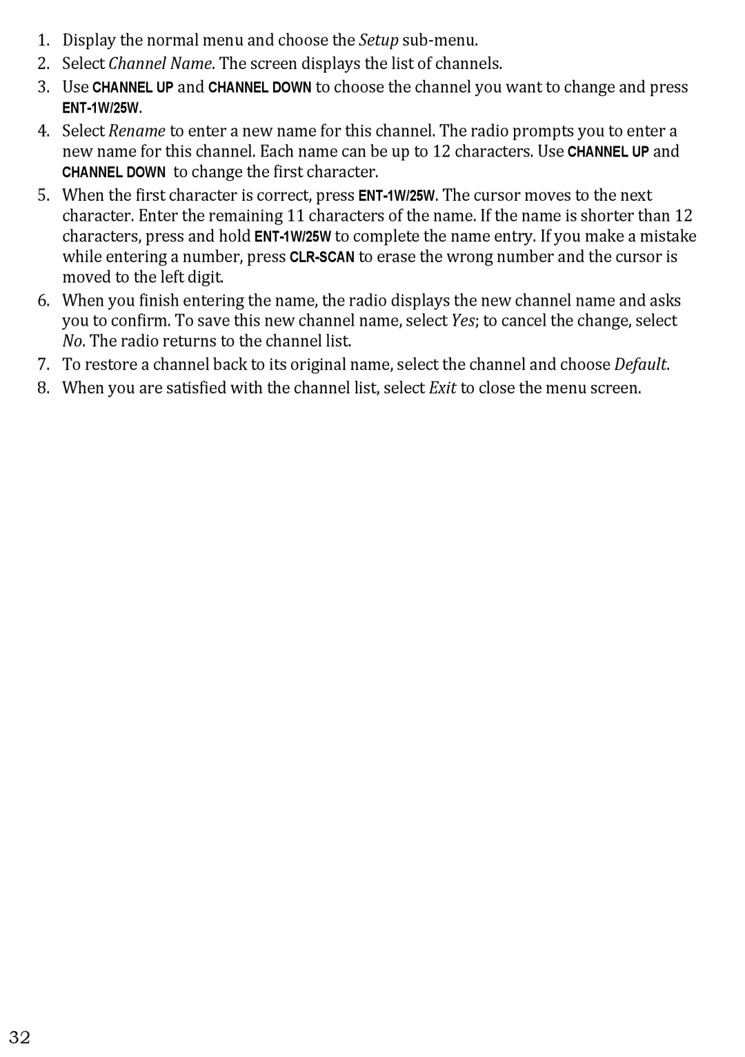
Page 36


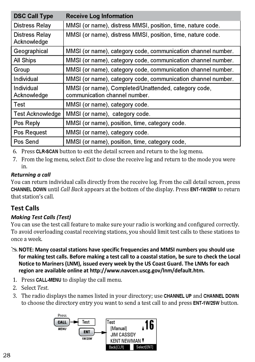
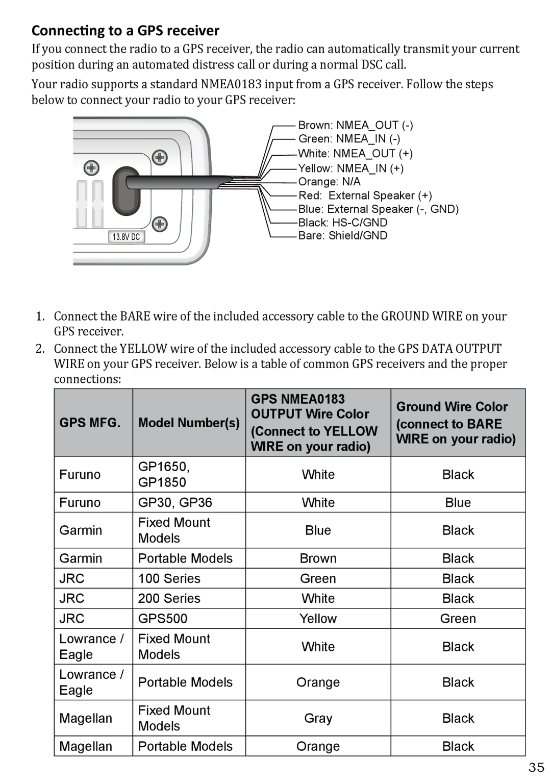
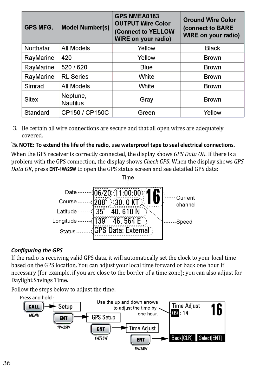
GPS NMEA0183

Ground Wire Color

GPS MFG.

Model Number(s)

OUTPUT Wire Color

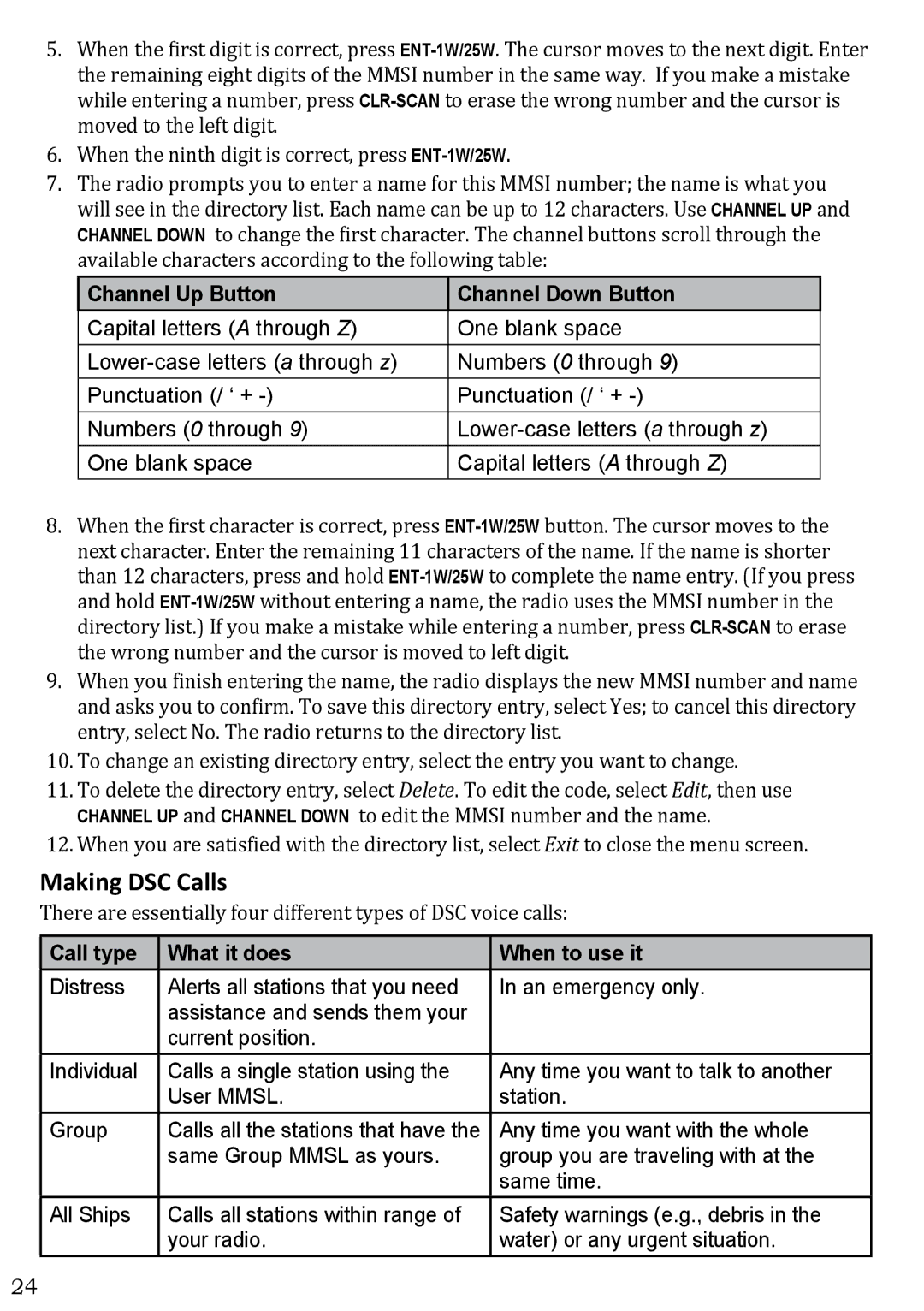
(connect to BARE

(Connect to YELLOW


WIRE on your radio)

WIRE on your radio)


Northstar

All Models

Yellow

Black

RayMarine

420

Yellow

Brown

RayMarine

520 / 620

Blue

Brown

RayMarine

RL Series

White

Brown

Simrad

All Models

White

Brown

Sitex

Neptune,

Gray

Brown

Nautilus


Standard

CP150 / CP150C

Green

Yellow

3.Be certain all wire connections are secure and that all open wires are adequately covered.

##NOTE: To extend the life of the radio, use waterproof tape to seal electrical connections.

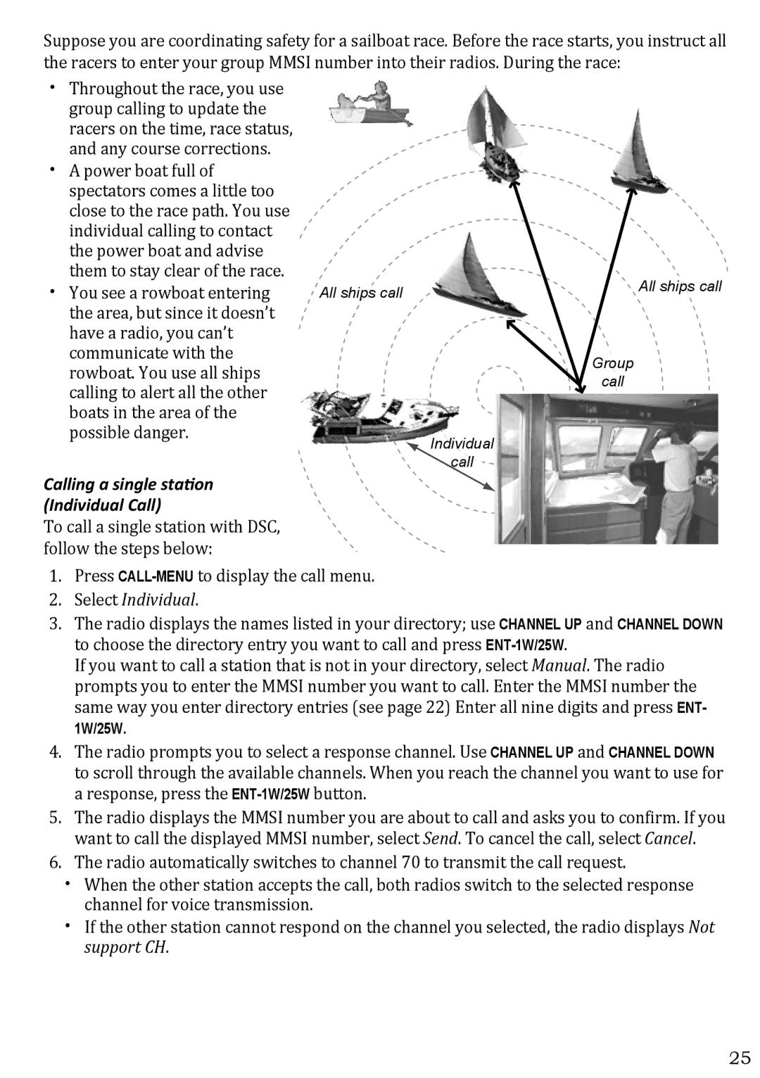
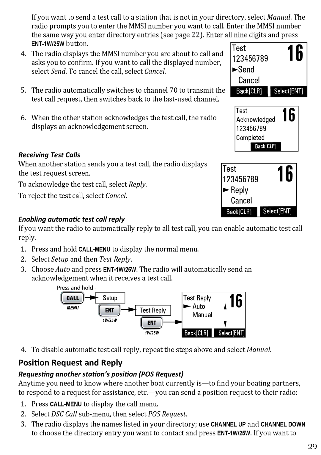
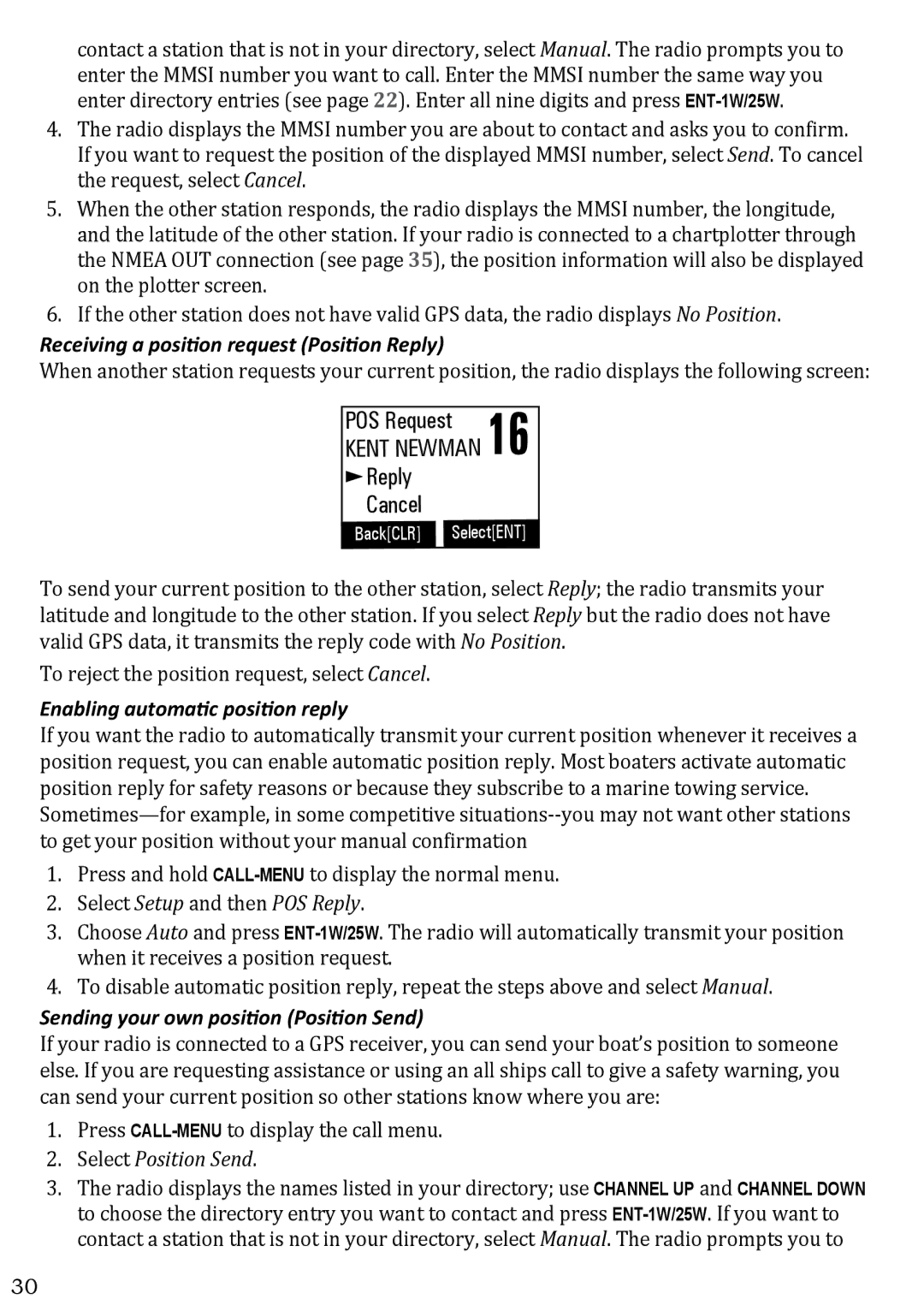
When the GPS receiver is correctly connected, the display shows GPS Data OK. If there is a problem with the GPS connection, the display shows Check GPS. When the display shows GPS Data OK, press ENT-1W/25Wto open the GPS status screen and see detailed GPS data:

Date

Course

Latitude

Longitude

Status


Time


06/20

11:00:00

16

channelCurrent

208o

30. 0 KT

35o

40. 610 N


139o

46. 564 E


Speed

GPS Data: External


Configuring the GPS

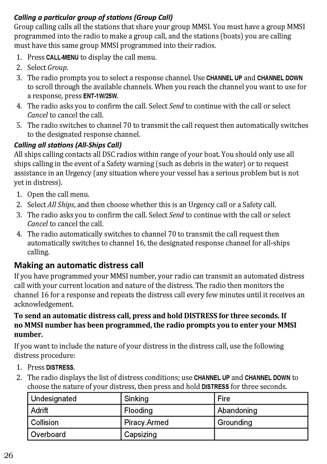
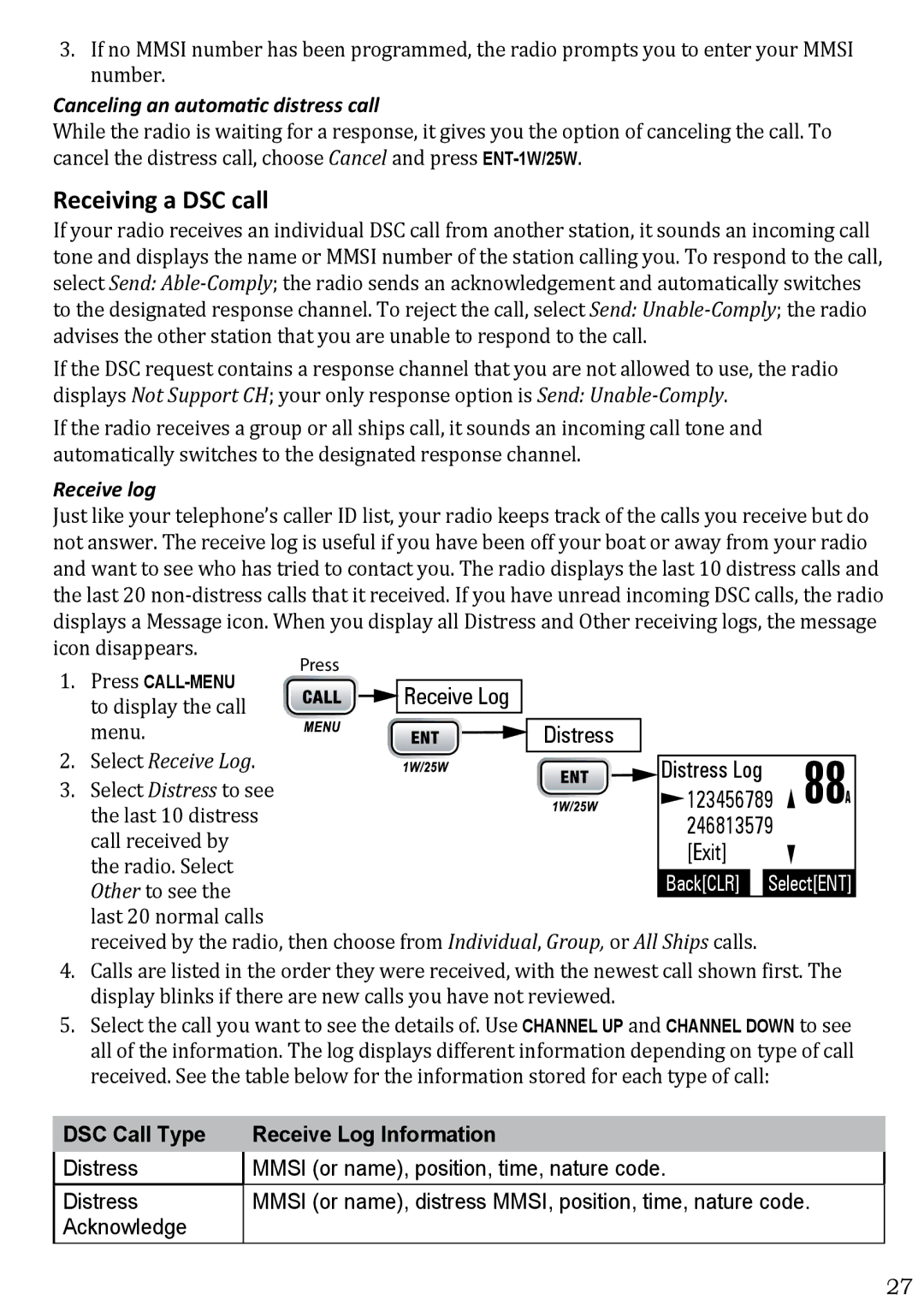
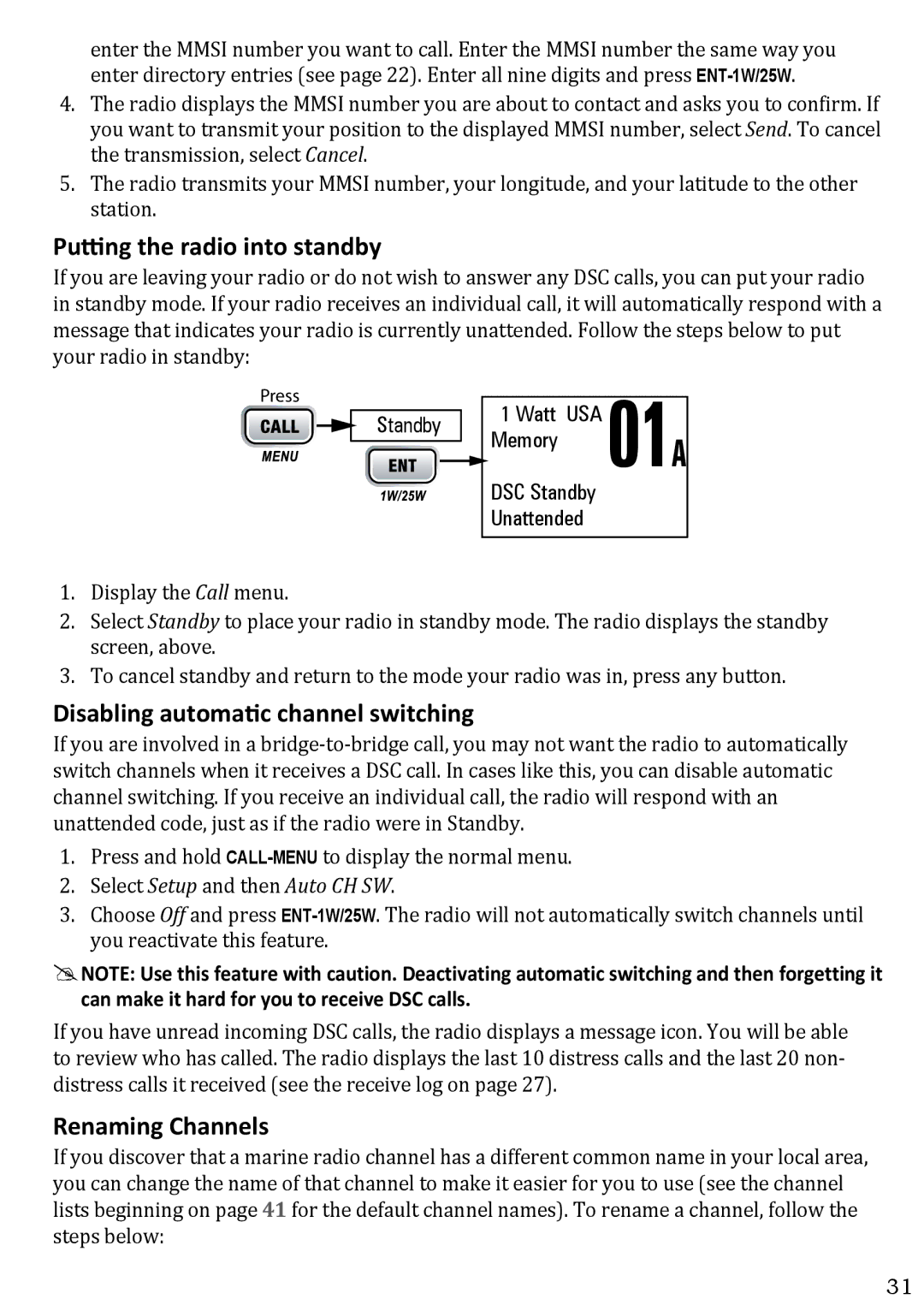
If the radio is receiving valid GPS data, it will automatically set the clock to your local time based on the GPS location. You can adjust your local time forward or back one hour if necessary (for example, if you are close to the border of a time zone); you can also adjust for Daylight Savings Time.

Follow the steps below to adjust the time:

Press and hold -

Setup

Use the up and down arrows


Time Adjust

16

to adjust the time by

09

: 14


one hour.

GPS Setup


Time Adjust

Back[CLR] Select[ENT]

36
Image 36
Contents DSC Marine Radio Making a Distress Call Making a Voice Distress CallFaire un appel de détresse Faire un appel de détresse vocalCómo hacer una llamada de apuro Cómo hacer una llamada de apuro por vozContents Features IntroductionManual overview ConventionsGetting Started What’s includedParts of the Radio Button Press to Press and hold toConnector/Cable Connects to For details, see Parts of the MicrophoneButton Press to Press and hold Setting the UIC Channel Mode USA/CAN/INT Mode What It Does Use It When To Turn it on./offHow It Works Turning on the RadioNormal mode operation Watch Mode What It Does Use It When To Turn it on./offUsing the radio in normal mode Normal mode with Weather Alert WatchNormal mode with Triple and Dual Watch Message MeaningScan mode Normal mode with both Weather Alert and Triple/Dual Watch08 10 11 12 13 15 17 Using the radio in scan mode Scan mode with Weather Alert WatchScan mode with Triple and Dual Watch Scan mode with both Weather Alert and Triple/Dual WatchWeather mode Using the radio in weather modeWeather mode with Weather Alert Watch Using Your Radio Using Your RadioSetting the volume Setting the squelch levelMaking a voice Mayday call Changing the channelBoosting the transmission power Choosing Triple Watch or Dual WatchUsing Fips codes for weather alerts Setting the GPS position manually Lamp adjustChanging display and sound options ContrastUsing Digital Selective Calling DSC Features What is DSC?Advanced DSC features What is an Mmsi number?Entering Mmsi numbers Individual or User Mmsi NumberUsing the Directory Group Mmsi numberCall type What it does When to use it Making DSC CallsChannel Up Button Channel Down Button Calling a single station Individual Call Select IndividualMaking an automatic distress call Calling a particular group of stations Group CallCalling all stations All-Ships Call Canceling an automatic distress call Receiving a DSC callReceive log DSC Call Type Receive Log InformationTest Calls Returning a callMaking Test Calls Test Position Request and Reply Receiving Test CallsEnabling automatic test call reply Requesting another station’s position POS RequestReceiving a position request Position Reply Enabling automatic position replySending your own position Position Send Disabling automatic channel switching Putting the radio into standbyRenaming Channels ENT-1W/25W Installing the Hardware Mounting the radioConnecting the radio Power Supply Requirements VHF Antenna RequirementsConnecting to a GPS receiver Ground Wire ColorConfiguring the GPS GPS Data ExternalConnecting to a Chartplotter Connecting to an External SpeakerMaintenance and Troubleshooting Problem Things to TryEngine Noise Suppression Specifications Radio SpecificationsTransmitter Reference Tables Channel descriptions and what they meanReceiver Channel name/description Used forUS Marine Channels and Frequencies Ch No RX Freq TX Freq Status Name on displayCanadian Marine Channels and Frequencies Ch No RX Freq TX Freq Status Name on display International Marine Channels and Frequencies Ch No RX Freq TX Freq Status Name on display Weather Channels and Frequencies US, CAN, and INT Emergency Alert System Same InformationCh No RX Freq Name on display Types of eventsFFW No Response Event Code WFWNmea Operation Nmea OutputNmea Input Basic radio guidelines Three Year Limited Warranty Page QUESTIONS?