
Section 6 - Technical Specifications
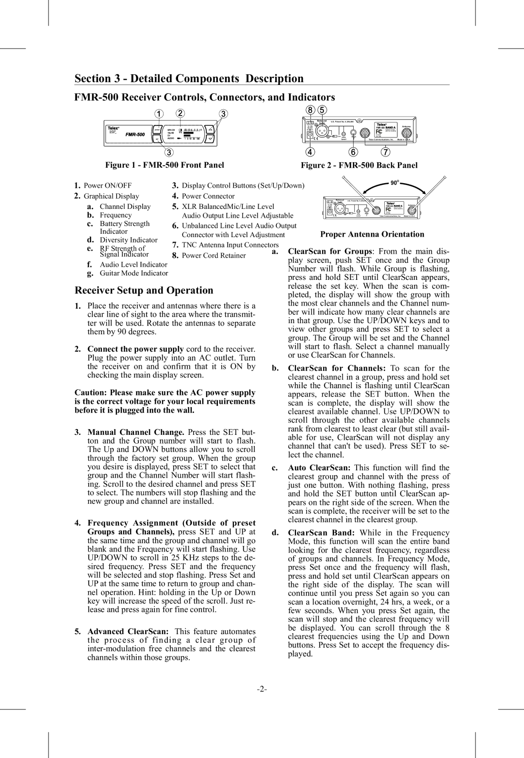
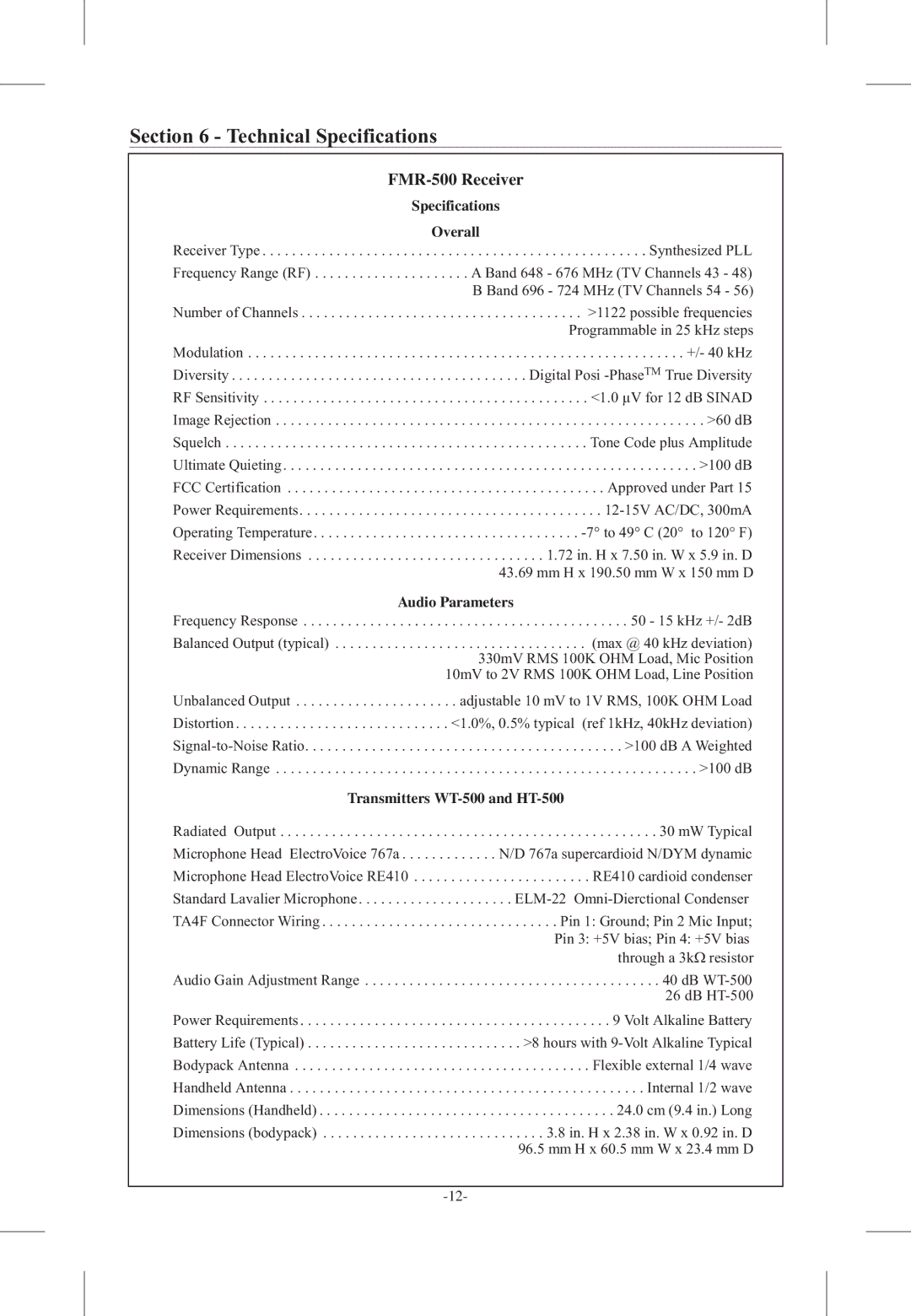
FMR-500 Receiver
Specifications
Overall
Receiver Type . . . . . . . . . . . . . . . . . . . . . . . . . . . . . . . . . . . . . . . . . . . . . . . . . . . . Synthesized PLL
Frequency Range (RF) . . . . . . . . . . . . . . . . . . . . . A Band 648 - 676 MHz (TV Channels 43 - 48) B Band 696 - 724 MHz (TV Channels 54 - 56)
Number of Channels . . . . . . . . . . . . . . . . . . . . . . . . . . . . . . . . . . . . . . >1122 possible frequencies Programmable in 25 kHz steps
Modulation . . . . . . . . . . . . . . . . . . . . . . . . . . . . . . . . . . . . . . . . . . . . . . . . . . . . . . . . . . . +/- 40 kHz Diversity . . . . . . . . . . . . . . . . . . . . . . . . . . . . . . . . . . . . . . . . Digital Posi
Receiver Dimensions . . . . . . . . . . . . . . . . . . . . . . . . . . . . . . . . 1.72 in. H x 7.50 in. W x 5.9 in. D 43.69 mm H x 190.50 mm W x 150 mm D
Audio Parameters
Frequency Response . . . . . . . . . . . . . . . . . . . . . . . . . . . . . . . . . . . . . . . . . . . . 50 - 15 kHz +/- 2dB
Balanced Output (typical) . . . . . . . . . . . . . . . . . . . . . . . . . . . . . . . . . . (max @ 40 kHz deviation) 330mV RMS 100K OHM Load, Mic Position 10mV to 2V RMS 100K OHM Load, Line Position
Unbalanced Output . . . . . . . . . . . . . . . . . . . . . . adjustable 10 mV to 1V RMS, 100K OHM Load Distortion . . . . . . . . . . . . . . . . . . . . . . . . . . . . . <1.0%, 0.5% typical (ref 1kHz, 40kHz deviation)
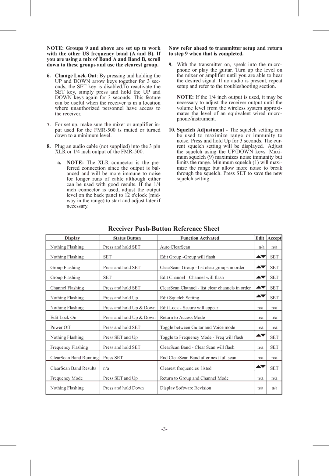
Transmitters WT-500 and HT-500
Radiated Output . . . . . . . . . . . . . . . . . . . . . . . . . . . . . . . . . . . . . . . . . . . . . . . . . . . 30 mW Typical Microphone Head ElectroVoice 767a . . . . . . . . . . . . . N/D 767a supercardioid N/DYM dynamic Microphone Head ElectroVoice RE410 . . . . . . . . . . . . . . . . . . . . . . . . RE410 cardioid condenser Standard Lavalier Microphone . . . . . . . . . . . . . . . . . . . . .
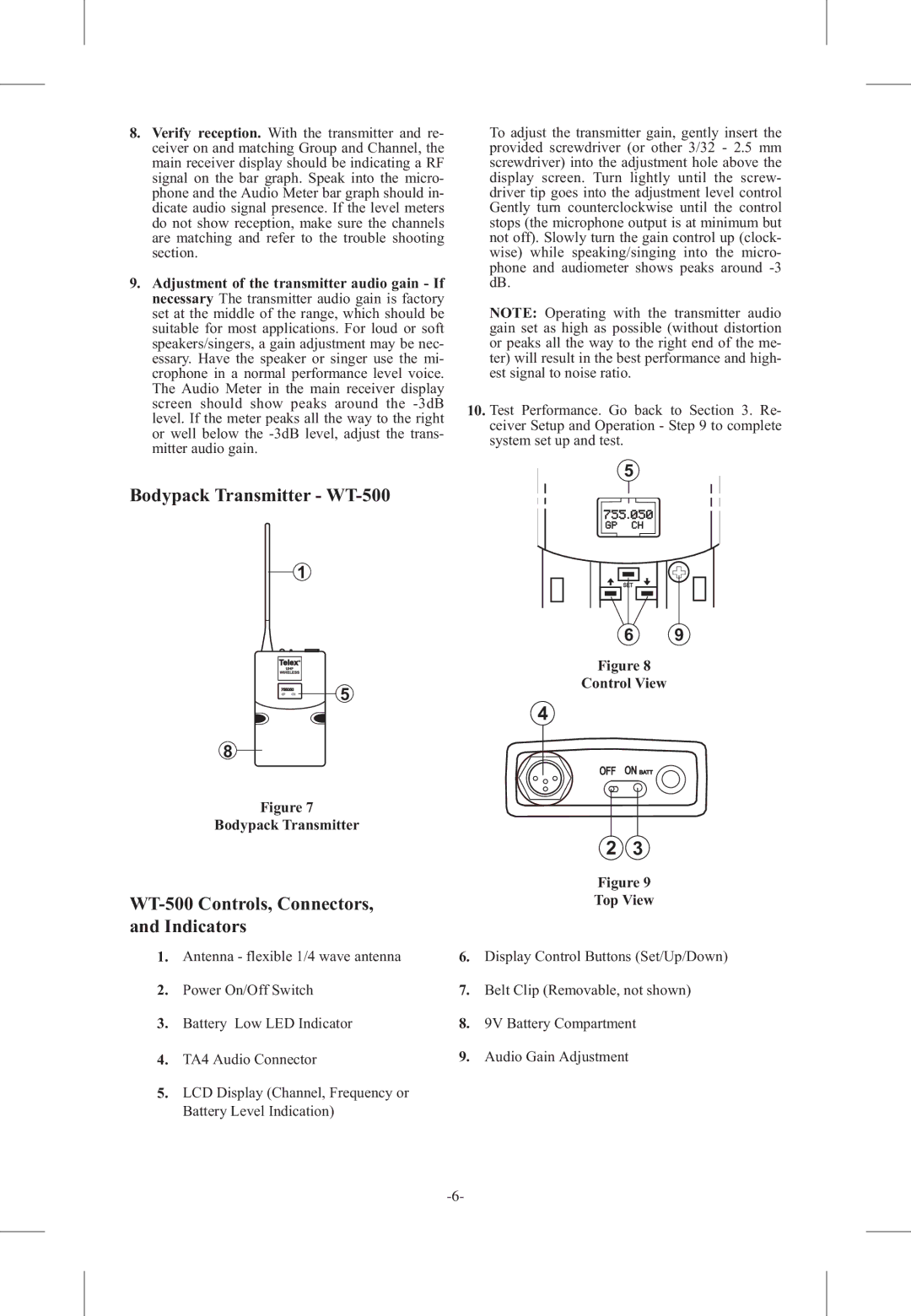
TA4F Connector Wiring . . . . . . . . . . . . . . . . . . . . . . . . . . . . . . . . Pin 1: Ground; Pin 2 Mic Input; Pin 3: +5V bias; Pin 4: +5V bias through a 3kΩ resistor
Audio Gain Adjustment Range . . . . . . . . . . . . . . . . . . . . . . . . . . . . . . . . . . . . . . . . 40 dB
Power Requirements . . . . . . . . . . . . . . . . . . . . . . . . . . . . . . . . . . . . . . . . . . 9 Volt Alkaline Battery Battery Life (Typical) . . . . . . . . . . . . . . . . . . . . . . . . . . . . . >8 hours with
Dimensions (bodypack) . . . . . . . . . . . . . . . . . . . . . . . . . . . . . . 3.8 in. H x 2.38 in. W x 0.92 in. D 96.5 mm H x 60.5 mm W x 23.4 mm D