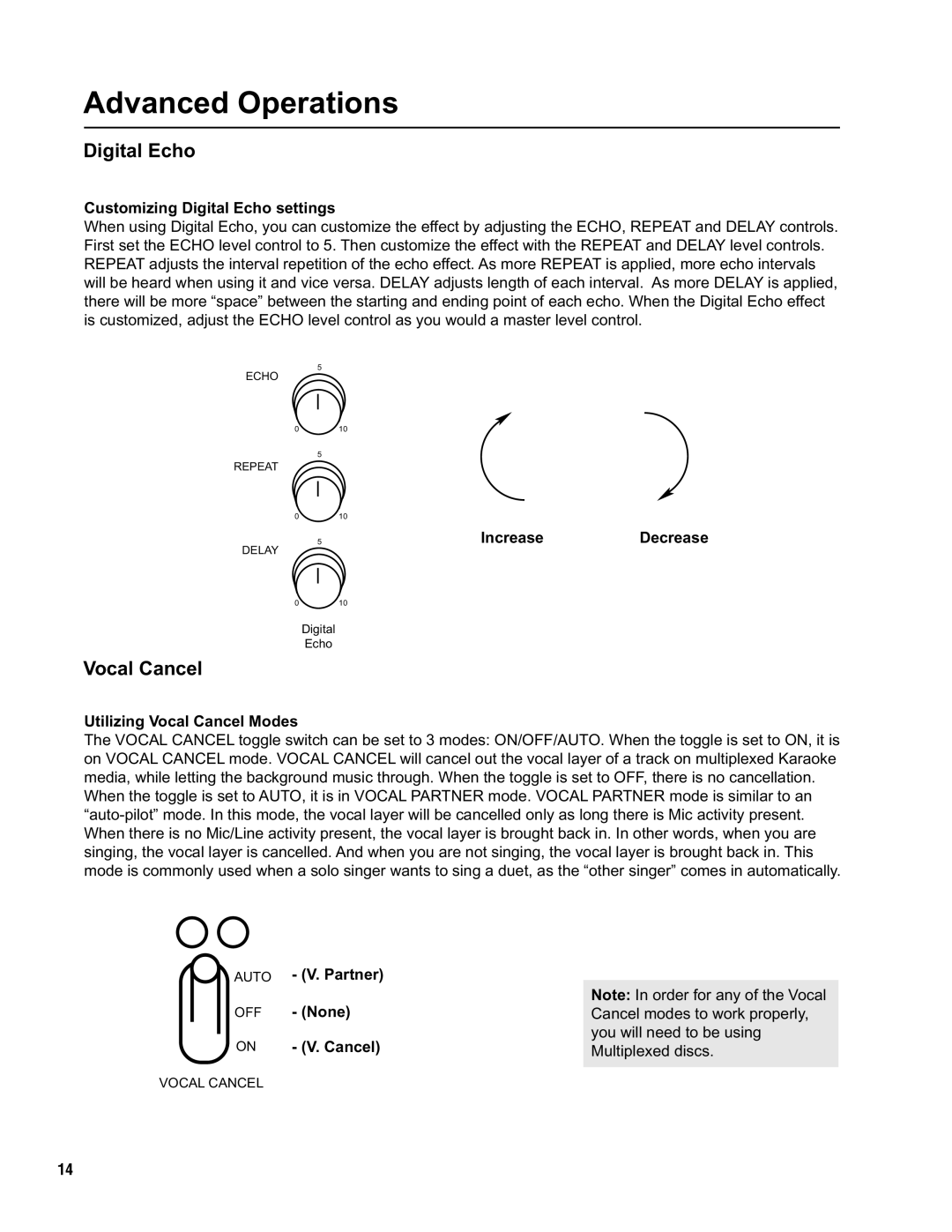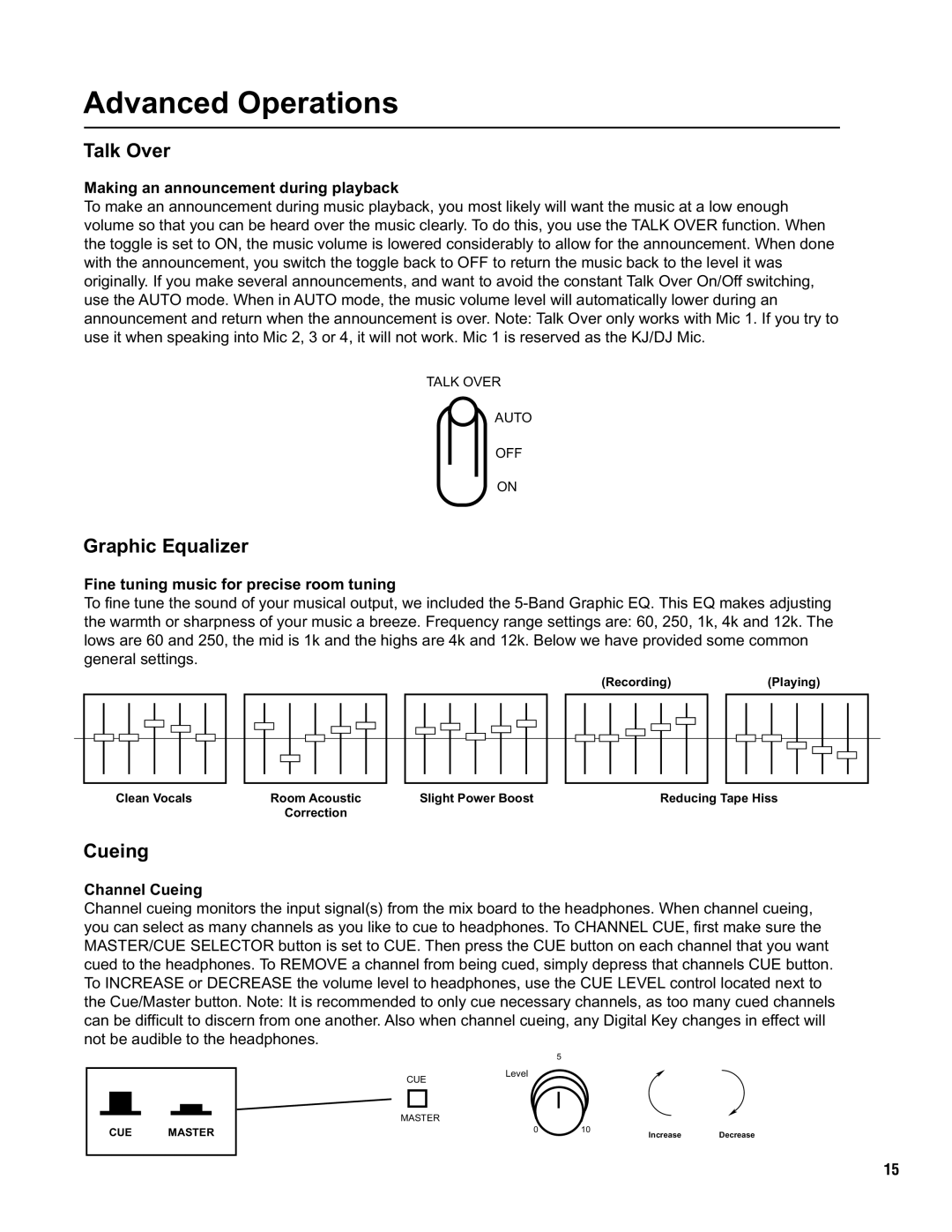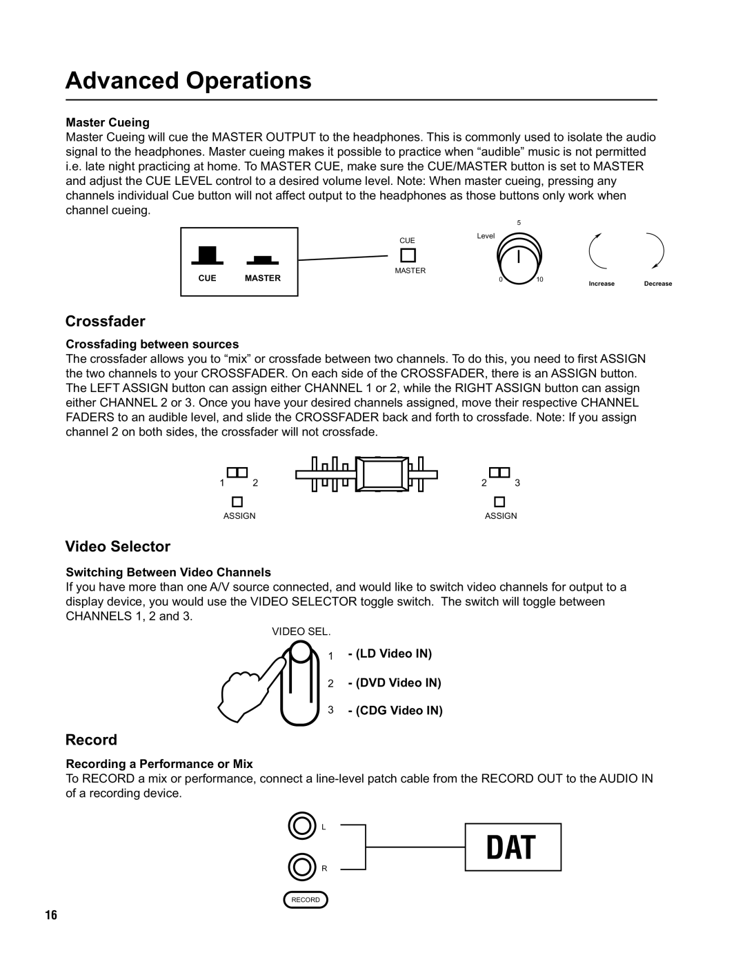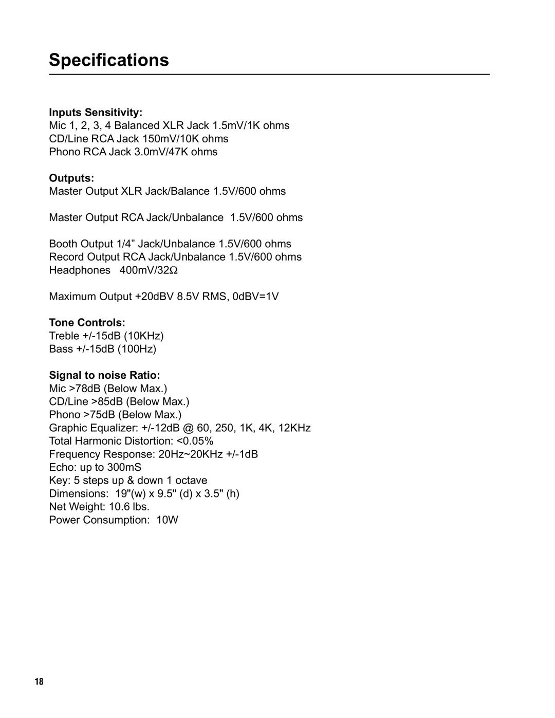
Master Panel Descriptions and Functions
(BALANCE) | 1 | (BALANCE) | (UNBALANCE) |
| 5Light (DC 12V) |
|
|
|
| ||
|
|
|
| L | 4 |
|
|
| 2 | 3 | 6 |
|
|
|
| R | |
|
|
|
| POWER | |
|
|
|
|
| |
MASTER L |
| MASTER R | MASTER | RECORD | PHONES |
|
| 5 |
7 CUE | Level | LEFT |
|
|
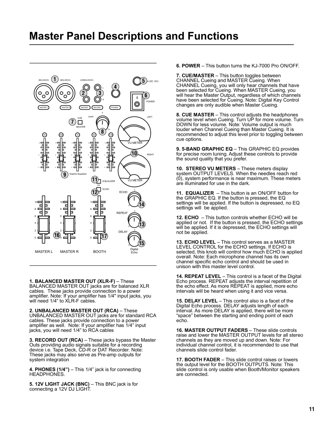
6. POWER – This button turns the |
7. CUE/MASTER – This button toggles between |
CHANNEL Cueing and MASTER Cueing. When |
CHANNEL Cueing, you will only hear channels that have |
been selected for Cueing. When MASTER Cueing, you |
will hear the Master Output, regardless of which channels |
have been selected for Cueing. Note: Digital Key Control |
changes are only audible when Master Cueing. |
8. CUE MASTER – This control adjusts the headphones |
volume level when Cueing. Turn UP for more volume. Turn |
DOWN for less volume. Note: Volume output is much |
60
12
6
0
12
6
0
MASTER
|
| 0 |
250 | 1K | 4K |
| 12 | 12 |
| 6 | 6 |
| 0 | 0 |
9 | Graphic Equalizer |
|
8 10
12K
12
6
0
VU METER
10 RIGHT
louder when Channel Cueing than Master Cueing. It is |
recommended to adjust this level prior to toggling between |
cue options. |
9. |
for precise room tuning. Adjust these controls to provide |
the sound quality that you prefer. |
10. STEREO VU METERS – These meters display |
system OUTPUT LEVELS. When the needles reach red |
11 |
ON
EQUALIZER | VU METER |
(0), system performance is near maximum. These meters |
are illuminated for use in the dark. |
12ON | ECHO |
| 5 |
| ECHO | ||
|
|
11. EQUALIZER – This button is an ON/OFF button for |
the GRAPHIC EQ. If the button is pressed, the EQ |
10 |
8 |
6 |
4 |
10 |
8 |
6 |
4 |
10
8
6
4
0
REPEAT
104
5
13
settings will be applied. If the button is depressed, no EQ |
settings will be applied. |
12. ECHO – This button controls whether ECHO will be |
applied or not. If the button is pressed, the ECHO settings |
2 |
0 |
2 |
16 0 |
2
0
17
0
DELAY
0
0
5
15
10
will be applied. If it is depressed, the ECHO settings will |
not be applied. |
13. ECHO LEVEL – This control serves as a MASTER |
LEVEL CONTROL for the ECHO settings. If ECHO is |
MASTER L MASTER R | BOOTH | Digital |
Echo | ||
|
|
|
1.BALANCED MASTER OUT
2.UNBALANCED MASTER OUT (RCA) – These UNBALANCED MASTER OUT jacks are for standard RCA cables. These jacks provide connection to a power amplifier as well. Note: If your amplifier has 1/4” input jacks, you will need 1/4” to RCA cables
3.RECORD OUT (RCA) – These jacks bypass the Master Outs providing audio signals suitable for a recording device i.e. Tape Deck,
4.PHONES (1/4”) – This 1/4” jack is for connecting
HEADPHONES.
5.12V LIGHT JACK (BNC) – This BNC jack is for connecting a 12V DJ LIGHT.
selected, this knob will control how much ECHO is applied |
overall. Note: Each microphone channel has its own |
channel specific echo control and should be used in |
unison with this master level control. |
14. REPEAT LEVEL – This control is a facet of the Digital |
Echo process. REPEAT adjusts the interval repetition of |
the echo effect. As more REPEAT is applied, more echo |
intervals will be heard when using it and vice versa. |
15. DELAY LEVEL – This control also is a facet of the |
Digital Echo process. DELAY adjusts length of each |
interval. As more DELAY is applied, there will be more |
“space” between the starting and ending point of each |
echo. |
16. MASTER OUTPUT FADERS – These slide controls |
raise and lower the MASTER OUTPUT levels for all stereo |
channels as they are moved up and down. Note: For |
individual channel control, it is recommended to use that |
channels slide control fader. |
17. BOOTH FADER – This slide control raises or lowers |
the output level for the BOOTH OUTPUTS. Note: This |
slide control is only usable when Booth/Monitor speakers |
are connected. |
11
