Invacare Arrow FWD, MWD, RWD Repositioning Mkiv Joystick VAN Seat Models Figure, Electronics

Page 61

ELECTRONICS

PROCEDURE 13

This Procedure Includes the Following:

Repositioning MKIV Joystick - Van Seat Models Removing/Installing MKIV Controller

WARNING

After ANY adjustments, repair or service and BEFORE use,makesurethatallattachinghardwareistightened securely - otherwise injury or damage may result.

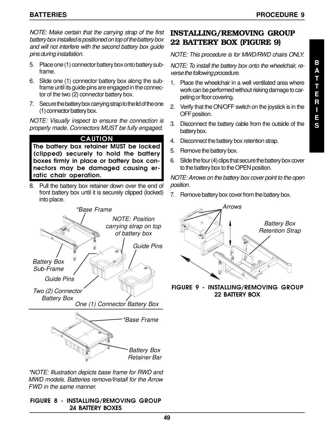
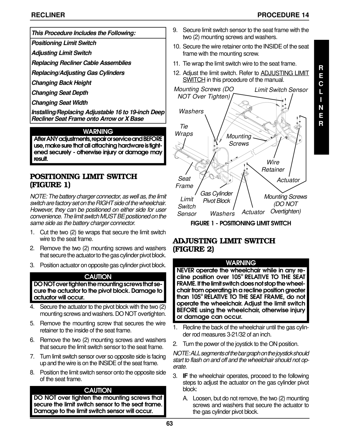
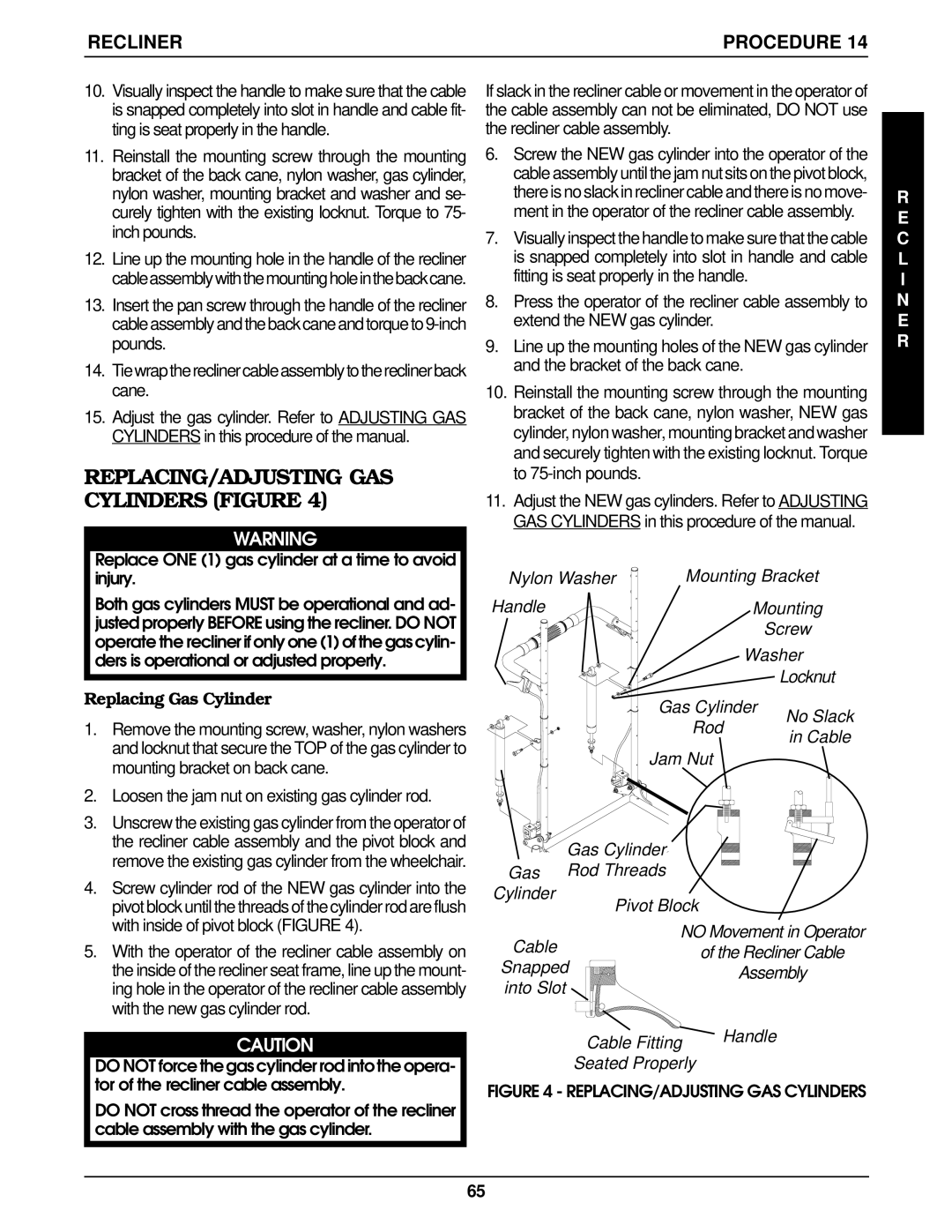
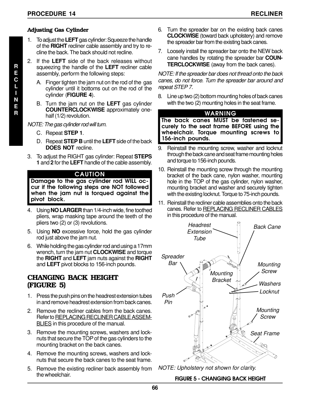
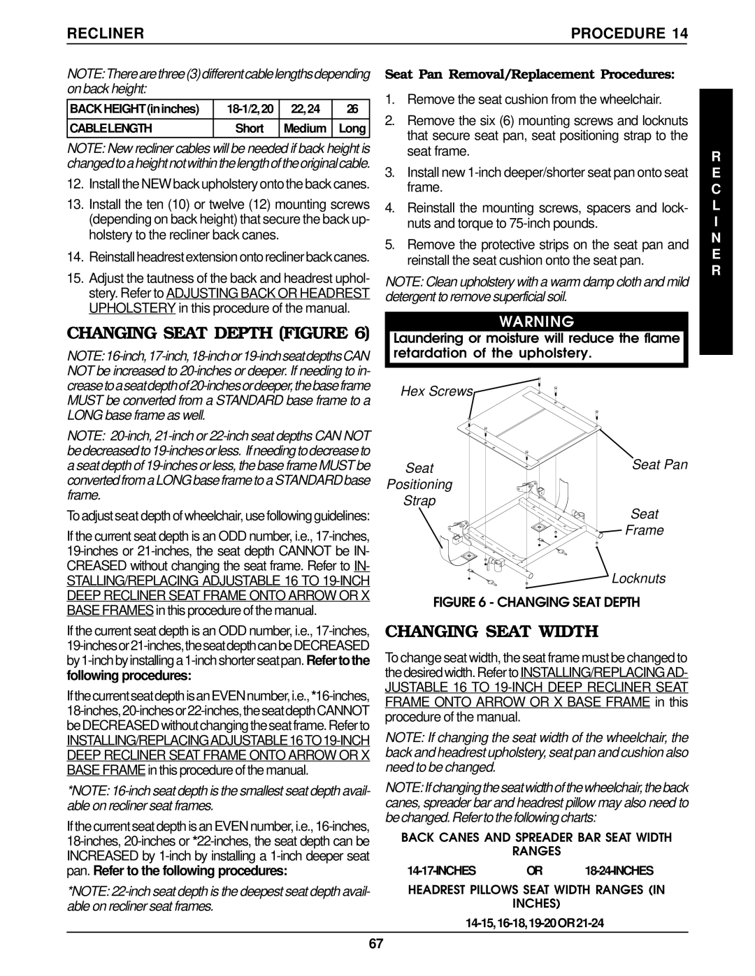
REPOSITIONING MKIV JOYSTICK - VAN SEAT MODELS (FIGURE 1)

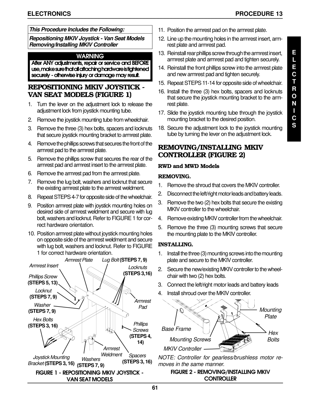
1.Turn the lever on the adjustment lock to release the adjustment lock from joystick mounting tube.

2.Remove the joystick mounting tube from wheelchair.

3.Remove the three (3) hex bolts, spacers and locknuts that secure joystick mounting bracket to armrest plate.

4.Remove the phillips screws that secures the front of the armrest pad to the armrest plate.

5.Remove the phillips screw that secures the rear of the armrest pad and armrest insert to the armrest plate.

6.Remove the armrest pad from the armrest plate.

7.Remove the lug bolt, washers and locknut that secure the existing armrest plate to the armrest weldment.

8.Repeat STEPS 4-7 for opposite side of the wheelchair.

9.Position armrest plate with joystick mounting holes on desired side of armrest weldment and secure with lug bolt, washers and locknut. Refer to FIGURE 1 for cor- rect hardware orientation.

10.Position armrest plate without joystick mounting holes on opposite side of the armrest weldment and secure with lug bolt, washers and locknut. Refer to FIGURE 1 for correct hardware orientation.

Armrest Plate

Lug Bolt (STEPS 7, 9)

Armrest Insert


Locknuts


Phillips Screw


(STEPS 3,16)


(STEPS 5, 13)


Locknut


(STEPS 7, 9)


Armrest

Washer


Pad

(STEPS 7, 9)


Hex Bolts


Phillips

(STEPS 3, 16)


Screws


(STEPS 4,


14)


Armrest

Joystick Mounting

Washers

Weldment Spacers


Bracket (STEPS 3, 16)

(STEPS 3, 16)

(STEPS 7, 9)

FIGURE 1 - REPOSITIONING MKIV JOYSTICK -

VAN SEAT MODELS

11.Position the armrest pad on the armrest plate.

12.Line up the mounting holes in the armrest insert, arm- rest plate and armrest pad.

13.Reinstall rear phillips screw through the armrest insert, armrest plate and armrest pad and tighten securely.

14.Reinstall the front phillips screw into the armrest plate and new armrest pad and tighten securely.

15.Repeat STEPS 11-14 for opposite side of wheelchair.

16.Install the three (3) hex bolts, spacers and locknuts that secure the joystick mounting bracket to the arm- rest plate.

17.Slide the joystick mounting tube through the joystick mounting bracket to the desired position.

18.Secure the adjustment lock to the joystick mounting tube by turning the lever on the adjustment lock.

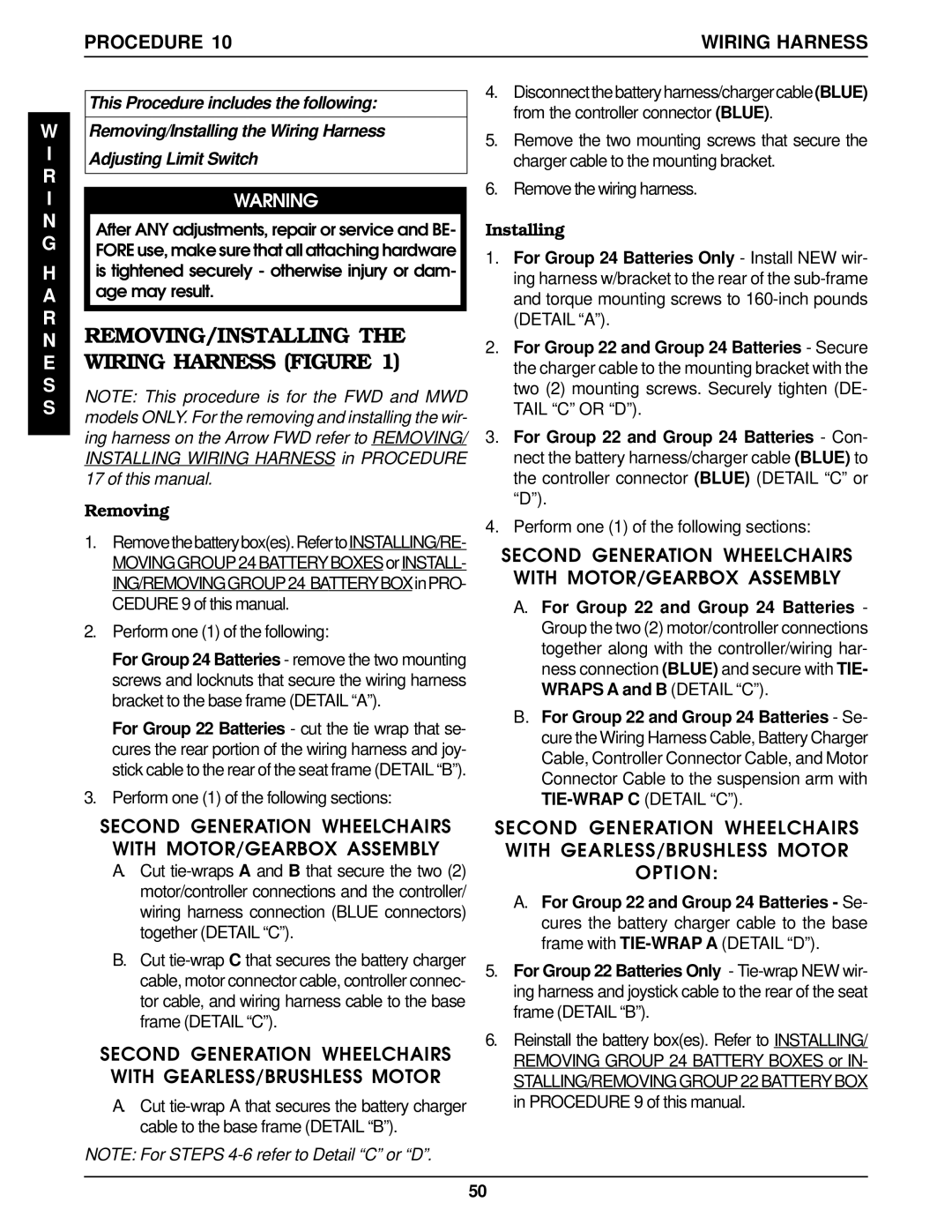
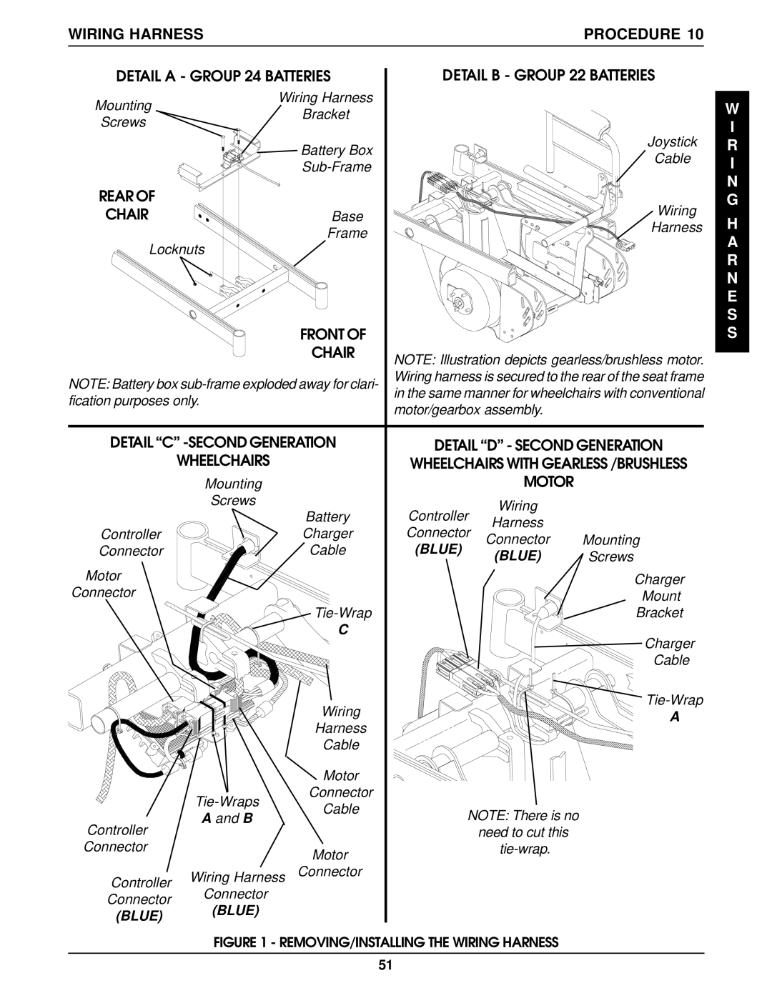
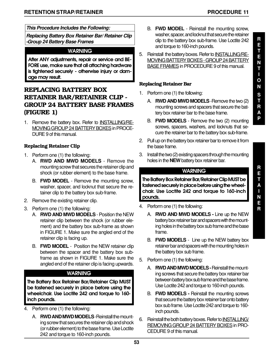
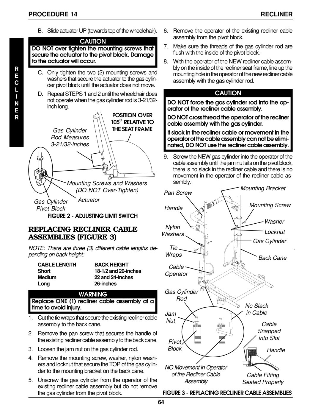
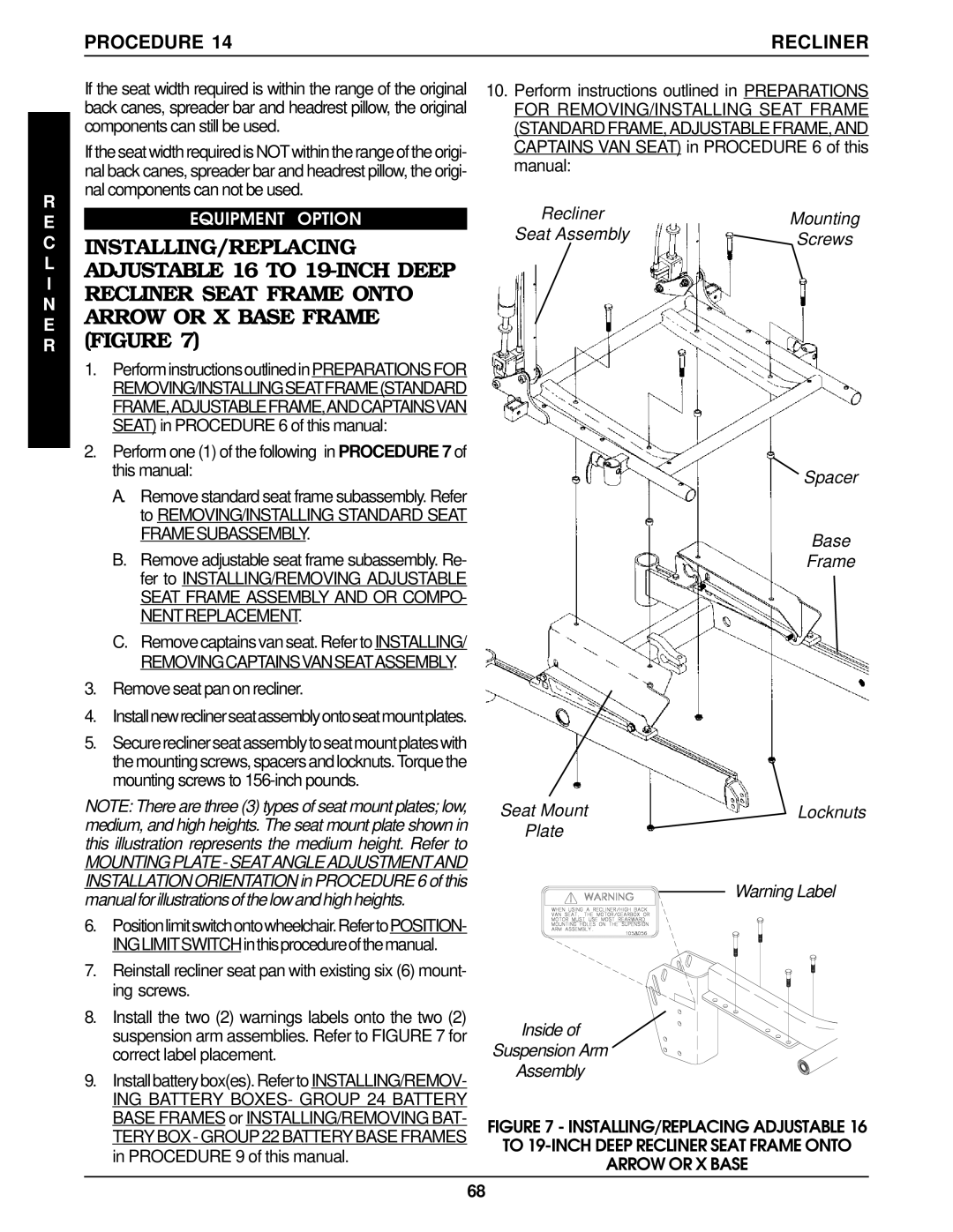
REMOVING/INSTALLING MKIV CONTROLLER (FIGURE 2)

RWD and MWD Models

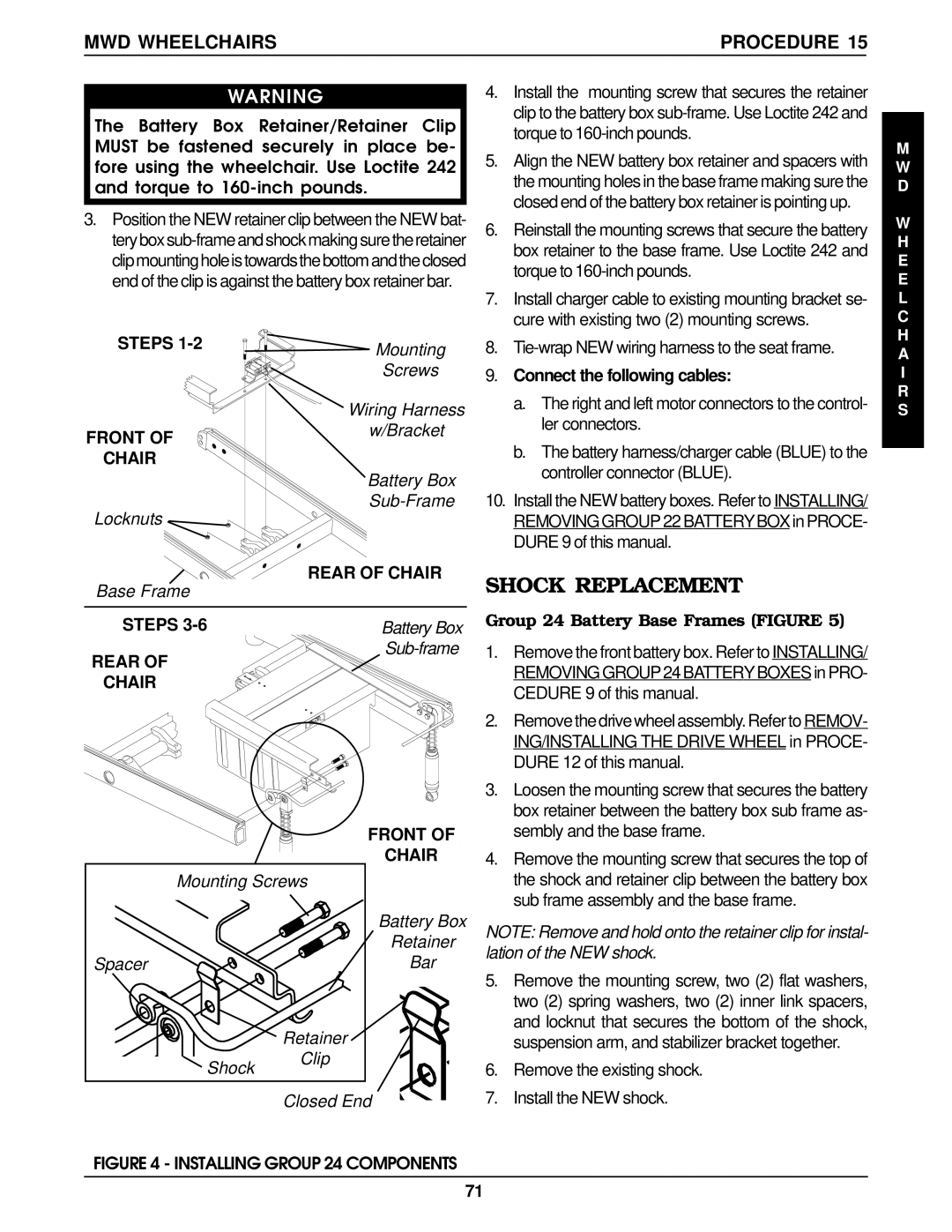
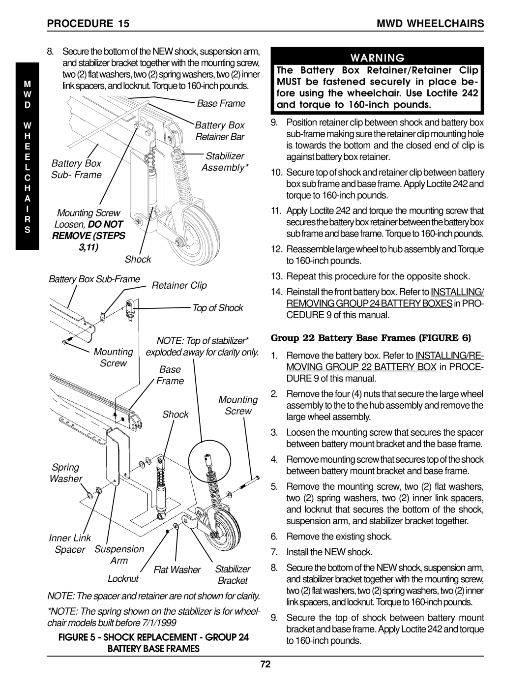
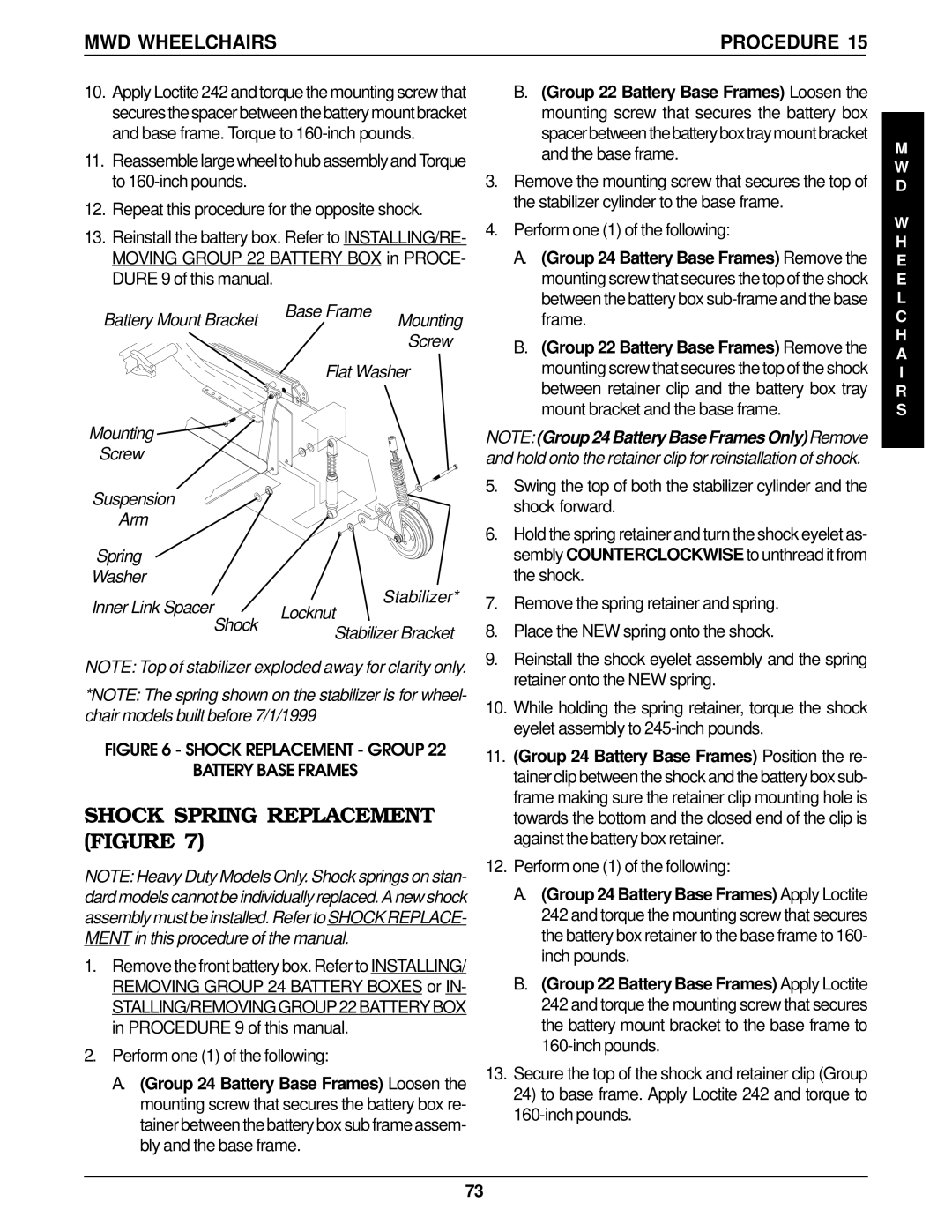
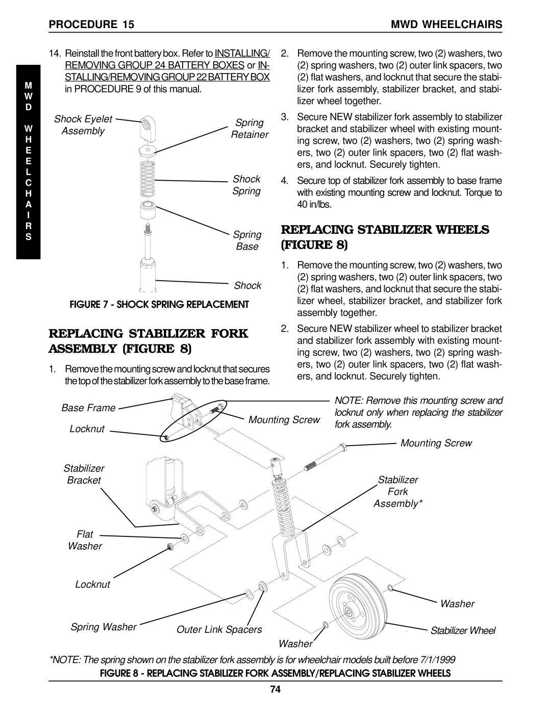
REMOVING.

1.Remove the shroud that covers the MKIV controller.

2.Disconnect the left/right motor leads and battery leads.

3.Remove the two (2) hex bolts that secure the existing MKIV controller to the wheelchair.

4.Remove existing MKIV controller from the wheelchair.

5.Remove the three (3) mounting screws that secure the mounting plate to the MKIV controller.

INSTALLING.

1.Install the three (3) mounting screws into the mounting plate and secure to the MKIV controller.

2.Secure the new/existing MKIV controller to the wheel- chair with two (2) hex bolts.

3.Connect the left/right motor leads and battery leads

4.Install shroud over the MKIV controller.

Mounting

Plate

Base Frame

Hex


Mounting Screws

Bolts

MKIV Controller

NOTE: Controller for gearless/brushless motor re- moves in the same manner.

FIGURE 2 - REMOVING/INSTALLING MKIV

CONTROLLER

E L E C T R O N I C S

61

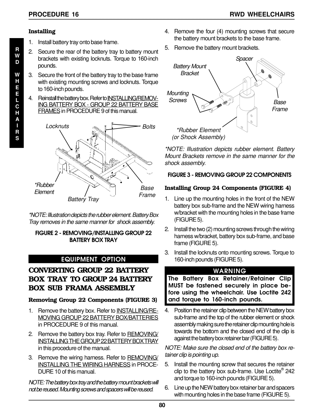
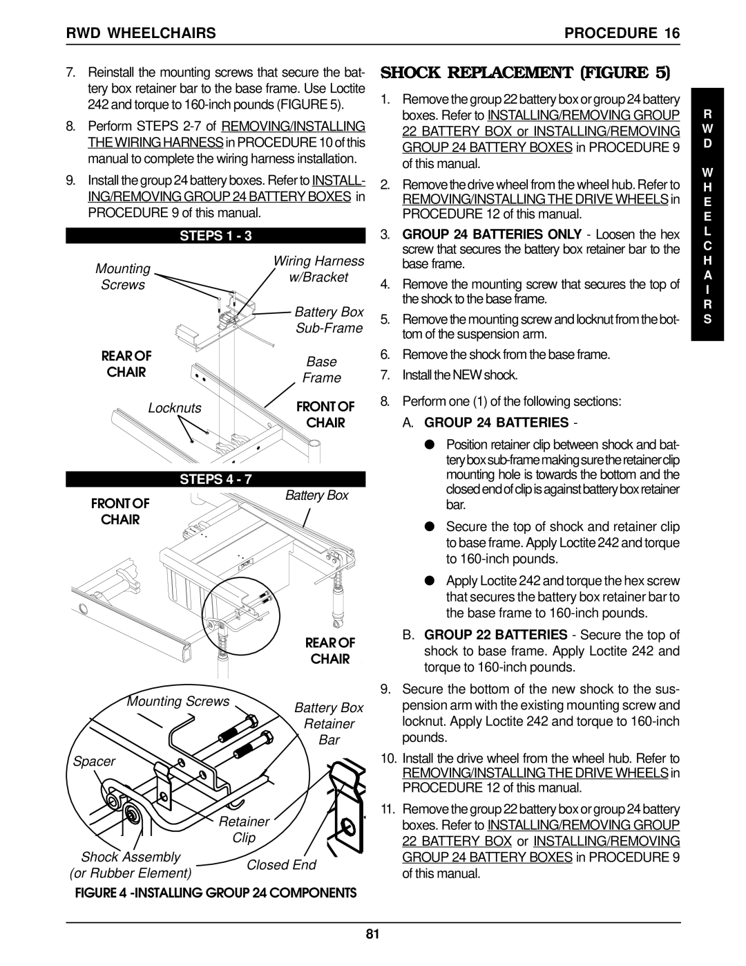
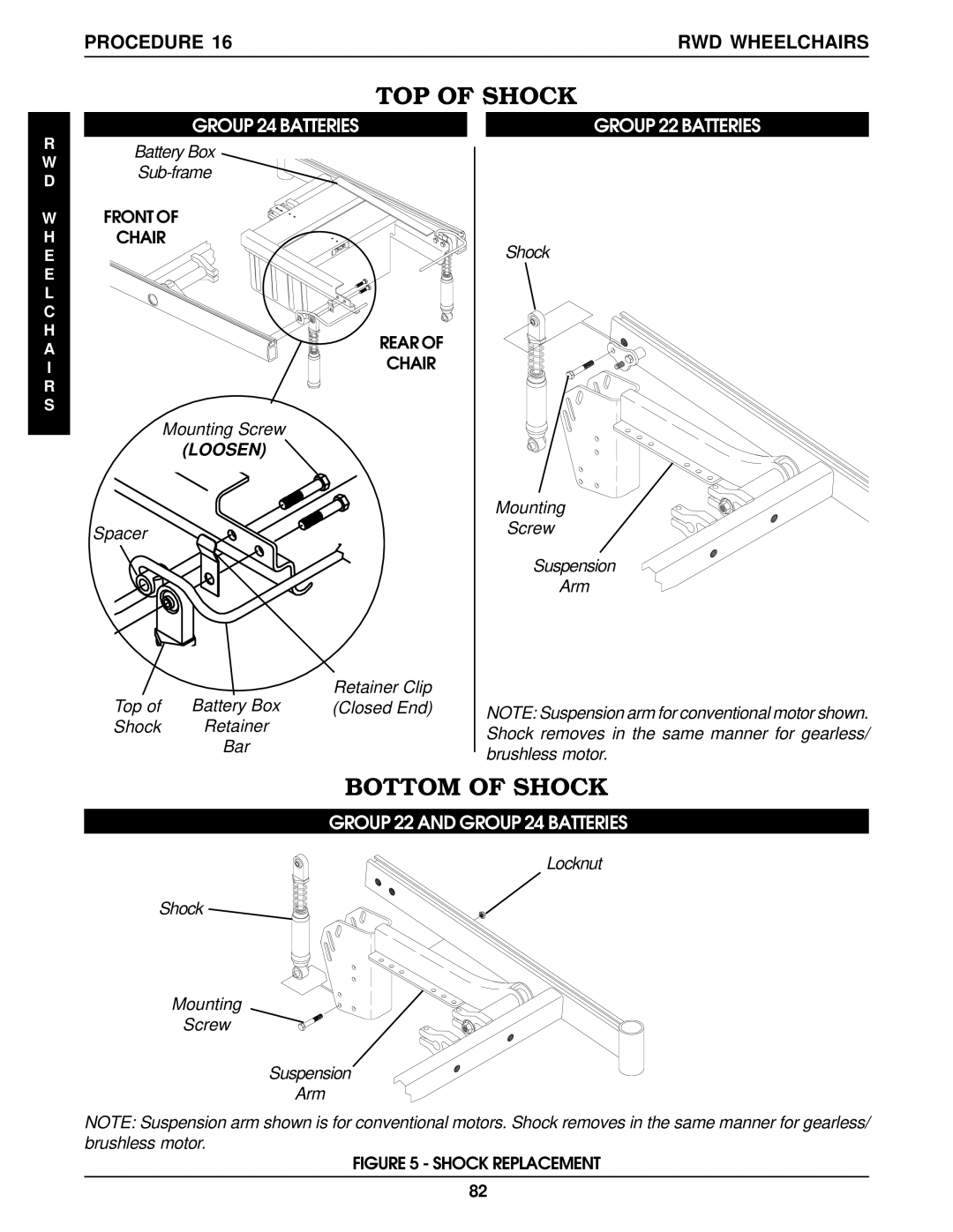
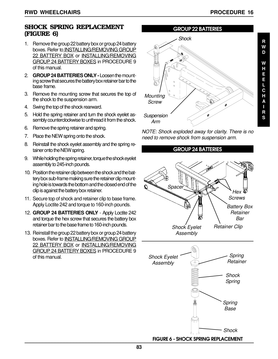
Image 61
Contents Storm Series Wheelchairs E C I a L T E S R N I N GTable of Contents Table of Contents Limited Warranty Specifications Specification SArrow FWD has a 400 lb. rating SpecificationsRepair or Service Information Procedure General GuidelinesMOTOR/GEARBOX General Guidelines ProcedureFWD Models MWD ModelsSuspension Arm Located on insideTroubleshooting Procedure Using Hydrometer to Check Battery Cells Lead Acid FigureBattery Charger Field Load Test FigureProcedure Troubleshooting Motor Testing FigureNumber of Floating Balls Will Vary According to ChargeOhmmeter Motor Connector ELECTRO-MECHANICAL Parking Brake Testing FigureCap Motor Pin Motor Connector Cap Motor Pin Motor Connector OhmmeterStandard Seat Frame Hardware Torque SpecificationsHardware Torque Specifications Procedure Adjustable Seat FrameCaptains VAN Seat Loctite and Torque to 75 in/lbs Torque to 156 in/lbsWheel Halves Inch WheelsPneumatic with Flat-Free Wheel Halves Torque to Pneumatic Wheel Halves 8 inch Torque to 18 in/lbsPneumatic with Flat-Free Inch Wheels Wheel HalvesWheel Halves Torque to In/lbs Torque to 156 in/lbs 1020 in/lbsTorque to 156 in/lbs Torque to 160 in/lbs Loctite Torque to 360 in/lbs Torque to 156 in/lbsThis Procedure Includes the Following Arms ProcedureReplacing Armrest Pads Captains VAN Seats Figure Replacing Captains VAN Seat Armrest Plate FigureReplacing Back Upholstery Figure Replacing Seat Positioning Y Strap Captains VAN SeatsH O L S T E R Y M E Seat Frame Procedure REMOVING/INSTALLING Standard Seat Frame Subassembly FigureReplacing Exact Same Size Standard Seat Frame Mounting ScrewsSeat Frame Adjustable Seat Frame FigureInches Inch Inch deep InchesTorque to A T M EChanging Seat Depth Between 12 and 15- Inches Figure Mounting Screws Torque to 75-inch pounds Changing Seat Width Standard and Adjustable Seat FrameStandard Seat Frame Side Spacers Center Seat WidthPounds Component ReplacementCoved Washer Center FrameInstalling Captains Van Seat INSTALLING/REMOVING Captains VAN Seat Assembly FigureRemoving Captains Van Seat Torque to Inch poundsCaptains Van Seat Adjustable FramesInstalling REMOVING/INSTALLING Seat PAN FigureRemove the seat cushion from the seat pan Locknut Quick Release PinInstallation Orientation Seat Angle AdjustmentSeat Dump Replacing Seat Mounting Plates Figure Base Frame ProcedureReplacing Seat Support Brackets Figure S E M EReplacing Seat Support Bracket T-NUTS Figure Procedure Base FrameMounting Screws Washer Seat Support Bracket BaseT-Nut Frame Channel Cover Seat Support Mounting ScrewBattery Charg er Charger Connector Mount Replacing Battery Charger Bracket and T-NUTRWD and MWD Models Figure Arrow FWD Model FigureMounting Screw Battery Charger Connector REMOVING/INSTALLING Seat Stop Screws FigureReplace the battery charger mount bracket and se Tightensecurely Reverse A, 3B or 3CBack Frame Procedure REMOVING/INSTALLING CJ Back Brackets FigureC K M E CJ Bracket MountsChanging Back Height Figure Procedure Back FrameHeavy Duty Models Mine if new back upholstery is neededSteps 6,11 Steps 2Steps 6,17 Steps 4,8Wheelchair to hold the insert in place Back Angle Adjustment FigureT T E R I E S Batteries ProcedureProcedure 9BATTERIES Connecting Battery CablesGroup 24 Batteries Battery Box Bottom TWO 2 Connector Batteryboxone 1 Connector BatteryboxBattery terminal ends Group 22 Battery Base Frames FigureRemove battery terminal caps from battery Bottom Tery Cable Rear Jumper Battery Single BatteryFront BoxBattery Discharge Indicator BDI in LCD Readout When to Charge Batteries FigureBattery Discharge Indicator BDI Description and Use of Battery ChargersRequired Items If one 1 battery is defective INSTALLING/REMOVING Group 24 Battery Boxes FigureRecommended Battery Types Cleaning Battery TerminalsINSTALLING/REMOVING Group 22 Battery BOX Figure Procedure Wiring Harness REMOVING/INSTALLING the E Wiring Harness FigureThis manual R N E S S Recline Angle 4 inches 61o Adjusting Limit Switch FigureReplacing Retainer Bar Retention STRAP/RETAINERReplacing Retainer Clip Perform one 1 the followingSpacer Locknuts Mounting Screws Battery Box Sub-Frame ProcedureSpacer Retainer Retainer ClipDrive Wheel Assembly Wheel Hub Four 4 Beveled Hex Nuts REMOVING/INSTALLING Drive Wheels FigureReplacing Pneumatic TIRES/ Tubes Drive WHEELS/CASTERS WHEELS/ MotorsApply Loctite 242 to the two 2 mounting screws WHEELS/MOTORSRepeat Steps 1-4 for opposite wheel lock bracket Gearbox SuspensionInstalling Casters REMOVING/INSTALLING Casters FigureReplacing Forks Figure Removing CastersMotor Connector Coupling Allen Easier access to the motor/controller connectionLocknut Spacer Washer ShockRemove motor with motor lock lever from suspen- sion arm Brake Release Shaft REMOVING/INSTALLING Motor GEARLESS/BRUSHLESSRepositioning Mkiv Joystick VAN Seat Models Figure REMOVING/INSTALLING Mkiv Controller FigureElectronics E C T R O N I C SArrow Fwd Model Switch Actuator Overtighten Sensor Washers Positioning Limit Switch FigureRecliner C L I N E RGas Cylinder Replacing Recliner Cable Assemblies FigureRod Measures 3-21/32-inches Mounting Screws and Washers Do not Over-Tighten Gas Cylinder ActuatorReplacing Gas Cylinder REPLACING/ADJUSTING GAS Cylinders FigureAdjusting Gas Cylinder Procedure ReclinerChanging Back Height Seat Pan Removal/Replacement Procedures Recliner ProcedureChanging Seat Depth Figure Changing Seat WidthInstallbatteryboxes.Referto INSTALLING/REMOV Plate Inside Suspension Arm AssemblyRemove seat pan on recliner Spacer Base Frame Seat MountBattery BOX Tray Figure REMOVING/INSTALLING GroupBattery BOX SUB-FRAME Figure MWD Wheelchairs ProcedureFront Locknuts Battery Mount Procedure MWD WheelchairsInstalling Group 24 Components Figure Frame Rear Lockn utsGroup 24 Battery Base Frames Figure Shock ReplacementSteps Large wheel assembly Shock Battery Box Sub-Frame Retainer Clip Top of ShockInstall the NEW shock Secure the top of shock between battery mountBattery Mount Bracket Base Frame Shock Spring Replacement FigureFlat Washer Mounting Screw Suspension Arm Spring WasherReplacing Stabilizer Wheels Figure Replacing Stabilizer Fork Assembly FigureShock Spring Base MWD Wheelchairsprocedure Adjusting Weight DistributionReplacing Stabilizer Cylinder Spring FigureAdjusting Spring Compression Adjusting Stabilizers FigureHeight Adjustment Replacing Suspension ARM Figure REMOVING/INSTALLING Gearbox Figure16-18 x 1-1/4-inch Mounting Screws 16-18 x 2-1/2-inch Motor Gearbox Suspension ArmTubular End Suspension Arm Entation. Bracket End of Suspension ArmSteps 6,10 Bracket End Suspension Arm Inner Link SpacerShock Replacement Removing/Installing Group 22 Battery Box TrayAnti-Tipper Wheel Replacement Sub-FrameBattery Tray Procedure RWD WheelchairsILocknutsBolts Rubber ElementRWD Wheelchairs Procedure Shock Replacement FigureMounting Wiring Harness Screws BracketShock Retainer Bar Spacer TopShock Mounting Screw Suspension Arm Locknut Shock Mounting Screw Suspension ArmGroup 24 Batteries only Apply Loctite RWD WheelchairsprocedureShock Hex Screw Battery Mount Bracket Rubber Element Replacement FigureTorque and Storm X wheelchairs Base Frame Mounting ScrewAdjusting Weight Distribution Figure REMOVING/INSTALLING GearboxAdjustment Options 16-18 2-inch 4-inchRepositioning the MOTOR/ Gearbox Figure Adjusting Weight Distribution ProcedureMounting Screws Washer Seat Support Bracket Base Frame Move gearbox to the position determine in StepStandard Position Lengthens the wheel Repositioning the GEARLESS/BRUSHLESS Motor ,14Suspension Arm Mounting Washer Screws Install the new suspension arm onto the base frame ANTI-TIPPER Wheel Replacement FigureAnti-Tip REMOVING/INSTALLING ANTI-TIP AssemblyLower Washers LocknutsREMOVING/INSTALLING Rear Shroud Figure REMOVING/INSTALLING Front Shroud FigureREMOVING/INSTALLING Side Shroud Assembly Figure FWD Wheelchairs ProcedureProcedure FWD Wheelchairs REMOVING/INSTALLING Counterweight FigureMounting Screw Washer Side Shroud Bracket Suspension Arm Handle Outside Lower EdgeCounterweight Replacing Group 24 Battery BOX SUB-FRAME FigureMounting Bracket Counterweight Bottom Shoulder Screw Bottom Shoulder Screw Bottom Slot in Mounting BracketBracket Mounting Screw REMOVING/INSTALLING Shocks FigureMounting Bracket Only Screw One 1 Shown For ClarityTIE ROD Replacement Figure Complete revolution on the TOP TWO 2 tie rods Locknut Arm Small Washer Large Mounting Screw Suspension ArmBattery wiring harness Detail C Sensor Cable Assembly Replacement FigureRemove the Existing sensor cable assembly Socket Suspension Screw ArmSHORT Motor GearboxReinstall the battery boxes. Refer to Installing Battery Box Sub Frame Sensor Washer Left Motor SensorTie Wrap C Replacing the Suspension ARM REMOVING/INSTALLING Wiring Harness FigureTie Wrap B Procedure FWD WheelchairsTie Wrap a 14 to 16 inches Inches 17 to 18 inches 19 to 20 inches Adjusting Weight Distribution For New Seat DepthDepth Footboard ADJUSTMENTS- DEPTH/HEIGHT/ANGLE FigureAngle HeightFootrest Angle Adjustments Right FWD Wheelchairs ProcedureHorizontal Position Cam Front Shroud Footrest105 106 Limtied Warranty Limited WarrantyOne InvacareWay ChedworthWay
Related manuals
Manual 150 pages 42.82 Kb

Arrow FWD, RWD, MWD specifications

Invacare is a renowned name in the field of mobility technologies, consistently innovating and enhancing the mobility devices market. Among its outstanding offerings are the Invacare MWD (Mid Wheel Drive), RWD (Rear Wheel Drive), and Arrow FWD (Front Wheel Drive) wheelchairs. Each of these models serves unique user needs, featuring distinct designs and functionalities.

The Invacare MWD is engineered for exceptional maneuverability. Its mid-wheel drive technology provides a centralized drive wheel, allowing for tight turns and easy navigation in confined spaces. This makes the MWD particularly suitable for indoor use, where space can be limited. The MWD also features advanced suspension systems, offering superior shock absorption. This results in a smoother ride over various terrains, enhancing user comfort and stability.

On the other hand, the Invacare RWD focuses on robust outdoor performance. With its rear-wheel drive configuration, this model has excellent traction and provides powerful acceleration. The RWD is designed for versatility, equipped with larger wheels that can handle uneven terrain while providing a stable ride. Its durable construction ensures enhanced longevity, making it an ideal choice for users who lead an active lifestyle and require reliable mobility solutions on rugged ground.

The Arrow FWD wheelchair brings another dimension with its front-wheel drive system. This design allows users to easily navigate obstacles as the front wheels can pivot over them. The Arrow FWD is particularly suited for both indoor and outdoor use, as it combines the agility of the MWD with the stability seen in the RWD. It features a compact design, making it easier for users to position themselves in various settings and social situations.

All three models utilize Invacare's cutting-edge technologies, such as advanced control systems and customizable seating options, enabling users to find their optimal comfort and support levels. The customizable features also cater to individual user needs, promoting enhanced independence.

In summary, Invacare’s MWD, RWD, and Arrow FWD wheelchairs represent an impressive blend of functionality, durability, and user-centric design. Each model presents its own unique technologies and attributes, allowing users to make informed choices based on their specific mobility requirements, lifestyle, and preferences. Whether navigating tight indoor spaces or tackling outdoor challenges, Invacare’s range of wheelchairs ensures that users can experience mobility with confidence and ease.