KX-TC1205RUB / KX-TC1205R UW / KX-TC1205R US / KX-TC1205RUF
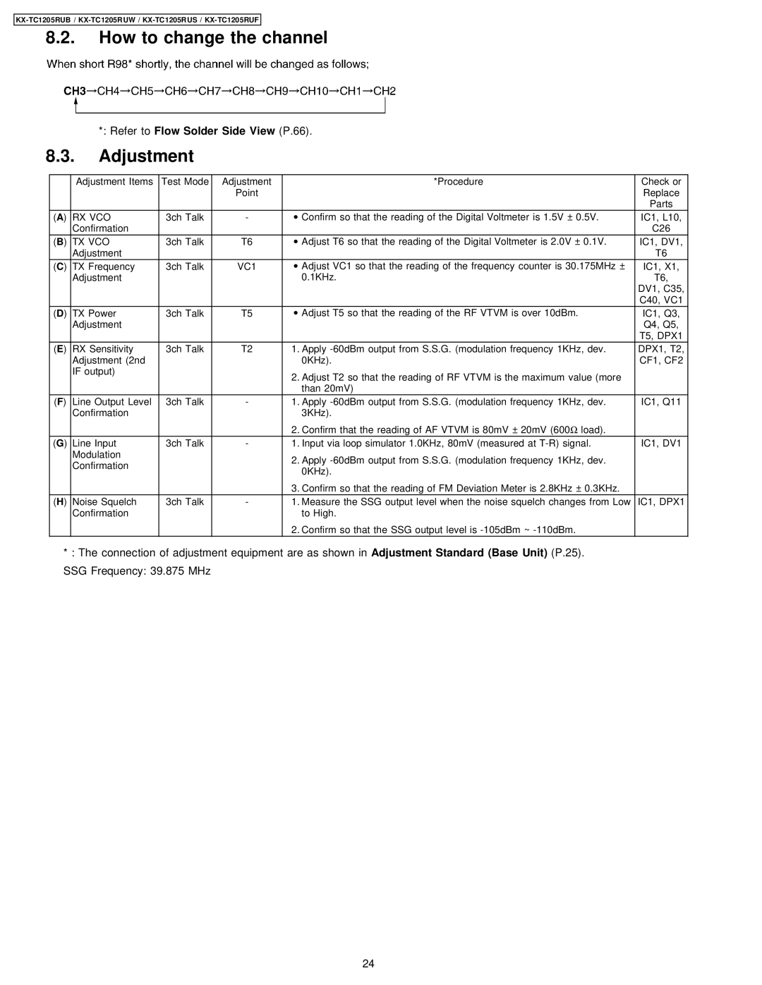
8.2.How to change the channel
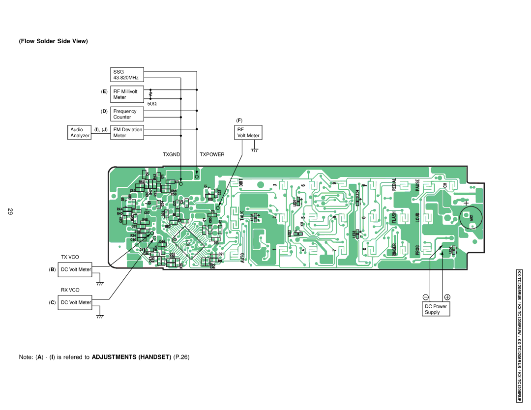
*: Refer to Flow Solder Side View (P.66).
8.3.Adjustment
| Adjustment Items | Test Mode | Adjustment | *Procedure | Check or |
|
|
| Point |
| Replace |
|
|
|
|
| Parts |
(A) RX VCO | 3ch Talk | - | ∙ Confirm so that the reading of the Digital Voltmeter is 1.5V ± 0.5V. | IC1, L10, | |
| Confirmation |
|
|
| C26 |
(B) TX VCO | 3ch Talk | T6 | ∙ Adjust T6 so that the reading of the Digital Voltmeter is 2.0V ± 0.1V. | IC1, DV1, | |
| Adjustment |
|
|
| T6 |
(C) TX Frequency | 3ch Talk | VC1 | ∙ Adjust VC1 so that the reading of the frequency counter is 30.175MHz ± | IC1, X1, | |
| Adjustment |
|
| 0.1KHz. | T6, |
|
|
|
|
| DV1, C35, |
|
|
|
|
| C40, VC1 |
(D) TX Power | 3ch Talk | T5 | ∙ Adjust T5 so that the reading of the RF VTVM is over 10dBm. | IC1, Q3, | |
| Adjustment |
|
|
| Q4, Q5, |
|
|
|
|
| T5, DPX1 |
(E) | RX Sensitivity | 3ch Talk | T2 | 1. Apply | DPX1, T2, |
| Adjustment (2nd |
|
| 0KHz). | CF1, CF2 |
| IF output) |
|
| 2. Adjust T2 so that the reading of RF VTVM is the maximum value (more |
|
|
|
|
|
| |
|
|
|
| than 20mV) |
|
(F) | Line Output Level | 3ch Talk | - | 1. Apply | IC1, Q11 |
| Confirmation |
|
| 3KHz). |
|
|
|
|
| 2. Confirm that the reading of AF VTVM is 80mV ± 20mV (600Ω load). |
|
(G) | Line Input | 3ch Talk | - | 1. Input via loop simulator 1.0KHz, 80mV (measured at | IC1, DV1 |
| Modulation |
|
| 2. Apply |
|
| Confirmation |
|
|
| |
|
|
| 0KHz). |
| |
|
|
|
|
| |
|
|
|
| 3. Confirm so that the reading of FM Deviation Meter is 2.8KHz ± 0.3KHz. |
|
(H) Noise Squelch | 3ch Talk | - | 1. Measure the SSG output level when the noise squelch changes from Low | IC1, DPX1 | |
| Confirmation |
|
| to High. |
|
2.Confirm so that the SSG output level is
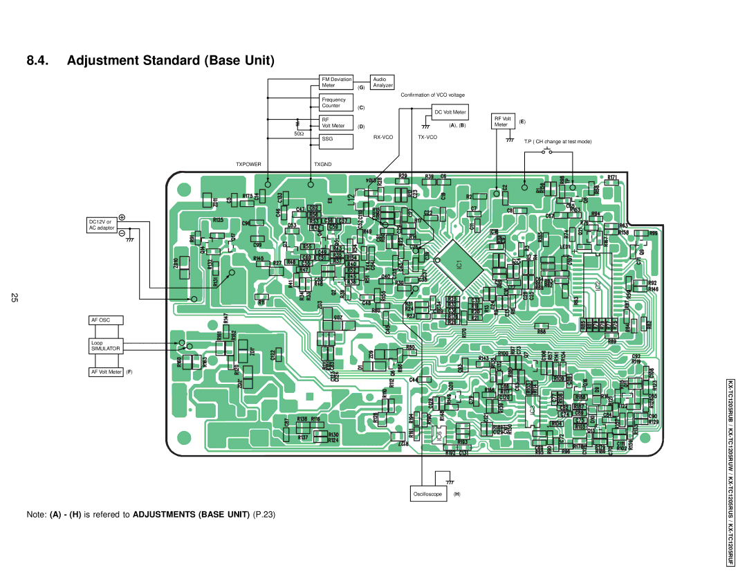
*: The connection of adjustment equipment are as shown in Adjustment Standard (Base Unit) (P.25). SSG Frequency: 39.875 MHz
24
