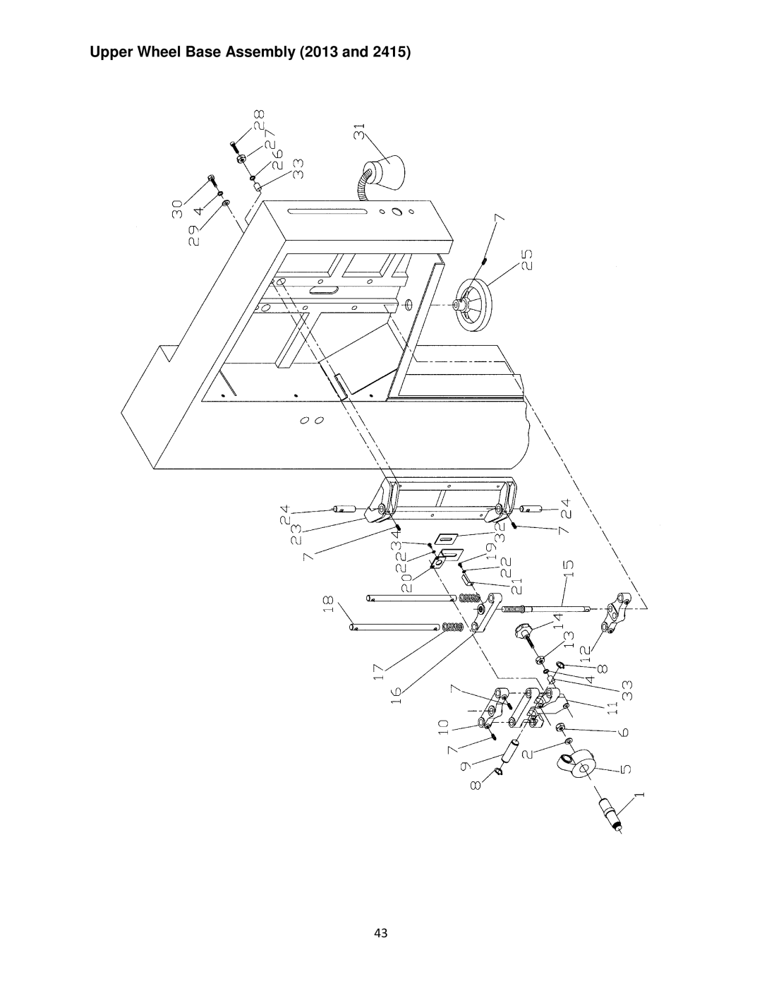
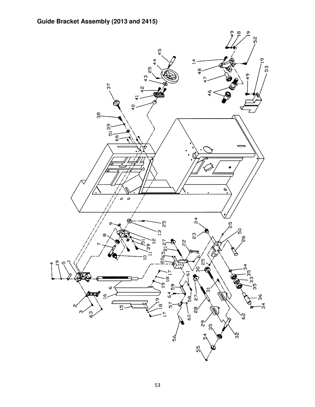
Parts List: Guide Bracket Assembly (2013 Band Saw)
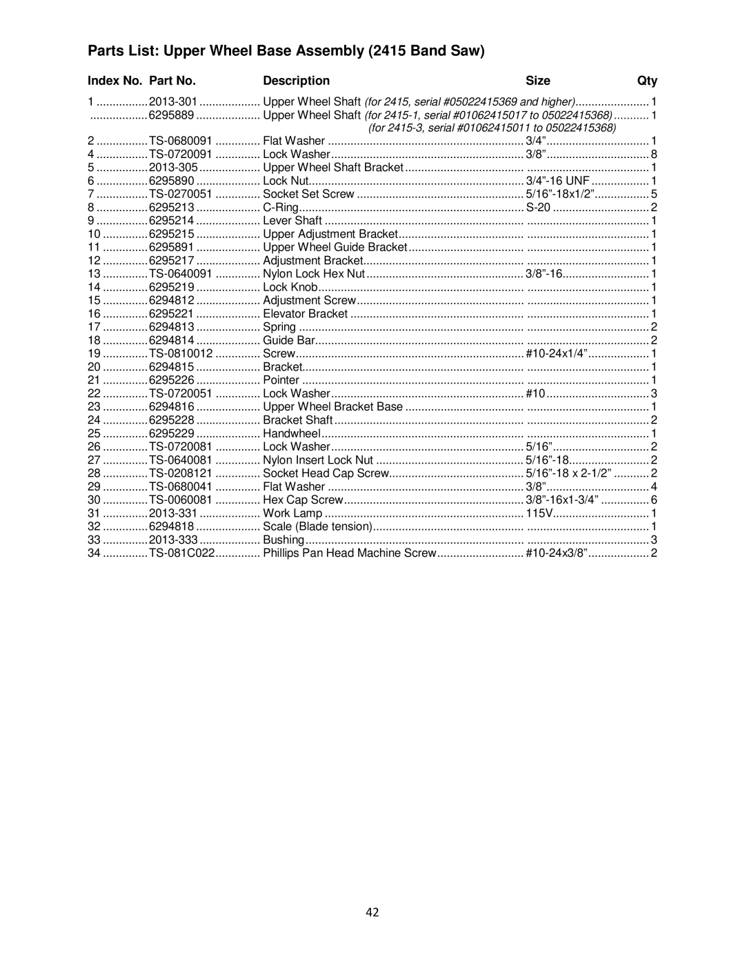
Index No. Part No. | Description | Size | Qty | |
1 | 6295275 | Guide Bar Case Bracket | ...................................... | 1 |
2 | 6295276 | Cover | ...................................... | 1 |
3 | Hex Cap Screw | 4 | ||
4 | Hex Cap Screw | 1 | ||
5 | 6295278 | Pointer | ...................................... | 1 |
6 | 6295279 | Guide Bar | ...................................... | 1 |
7 | 6295280 | Worm | ...................................... | 1 |
8 | 6295281 | Miniature Ball Bearing | 609 | 1 |
9 | 6295282 | 2 | ||
10 | 6295283 | Gear | ...................................... | 1 |
11 | Socket Head Cap Screw | 6 | ||
12 | 6295285 | Gear Base | ...................................... | 1 |
13 | 6295286 | Set Block | ...................................... | 1 |
14 | 6295287 | Thumb Screw | 1 | |
15 | 6295288 | Inner Blade Guard | ...................................... | 1 |
16 | 6295289 | Blade Guard | ...................................... | 1 |
17 | Hex Cap Screw | 4 | ||
18 | Lock Washer | 1/4” | 4 | |
19 | Flat Washer | 1/4” | 7 | |
20 | 6295291 | Guide Bar Bracket | ...................................... | 1 |
21 | Socket Set Screw | 1 | ||
22 | 6295293 | Locking Handle | 1/4”x3/4” | 1 |
23 | Socket Set Screw | M4x4 | 4 | |
24 | 6295294 | Knob | ...................................... | 2 |
25 | Socket Set Screw | 6 | ||
26 | 6295296 | Lever Shaft | ...................................... | 1 |
27 | 6295297 | Hand Nut | ...................................... | 2 |
28 | 6295298 | Bolt | ...................................... | 1 |
29 | 6295299 | Support Bearing Bracket (L) | ...................................... | 1 |
30 | 6295300 | Adjustment Bolt | ...................................... | 1 |
31 | Socket Head Cap Screw | 2 | ||
32 | 6295302 | Support Bearing Shaft | ...................................... | 1 |
33 | 6295303 | Spacer | ...................................... | 2 |
34 | 6295304 | 4 | ||
35 | 6295305 | Ball Bearing | 6202 | 5 |
36 | 6295306 | Shaft | ...................................... | 2 |
37 | 6295307 | Knob | 1 | |
38 | Socket Head Cap Screw | 4 | ||
39 | Lock Washer | 5/16” | 6 | |
40 | 6295308 | Ball Bearing | ...................................... | 1 |
41 | 6295309 | Bracket | ...................................... | 1 |
42 | Socket Head Cap Screw | 2 | ||
43 | 6295311 | Plastic Washer | ...................................... | 1 |
44 | 6295312 | Handwheel | ...................................... | 1 |
45 | 6295313 | Handle | ...................................... | 1 |
46 | 6295314 | Guide Wheel Assembly | ...................................... | 1 |
47 | 6295315 | Blade Support Shaft w/Bearing | ...................................... | 1 |
48 | 6295316 | Lower Guide Bracket | ...................................... | 1 |
49 | Hex Cap Screw | 2 | ||
50 | 6295318 | Bracket | ...................................... | 1 |
51 | Flat Washer | 5/16” | 4 | |
52 | Socket Head Cap Screw | 4 | ||
53 | 6295320 | Lower Blade Guard | ...................................... | 1 |
54 | 6295321 | Locking Nut | ...................................... | 1 |
55 | 6295322 | 1 | ||
56 | 6295323 | Air Nozzle | ...................................... | 1 |
57 | 6295324 | Hose Clamp | ...................................... | 1 |
58 | Screw | 1 | ||
59 | 6295325 | Bracket | ...................................... | 1 |
60 | Hex Nut | 1 | ||
49
