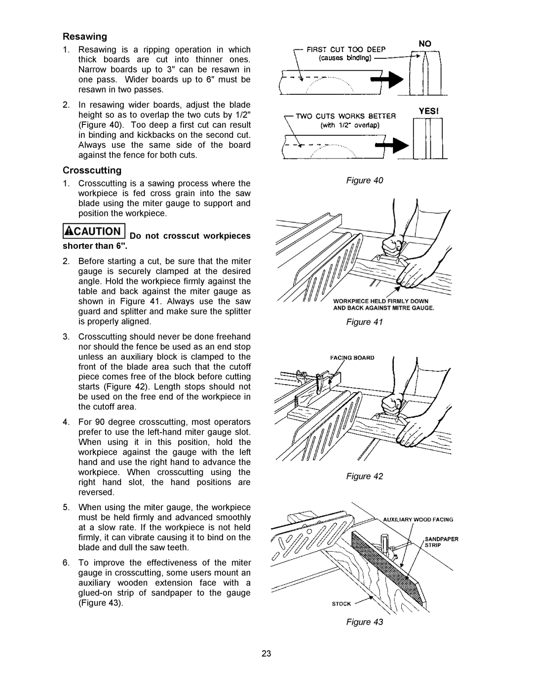
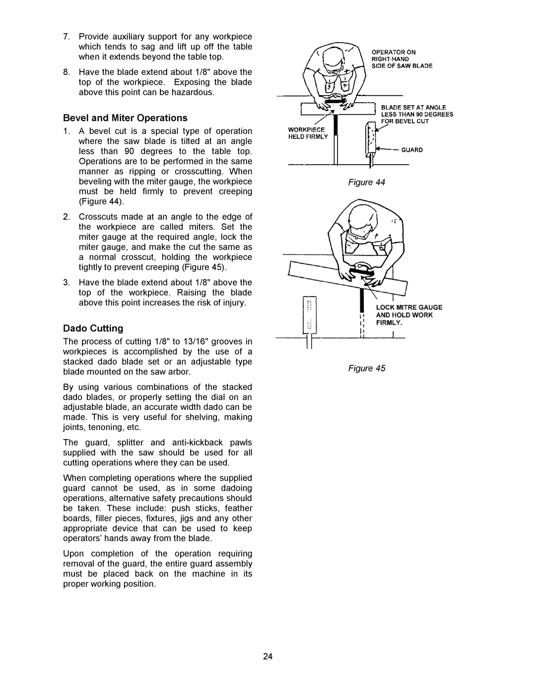
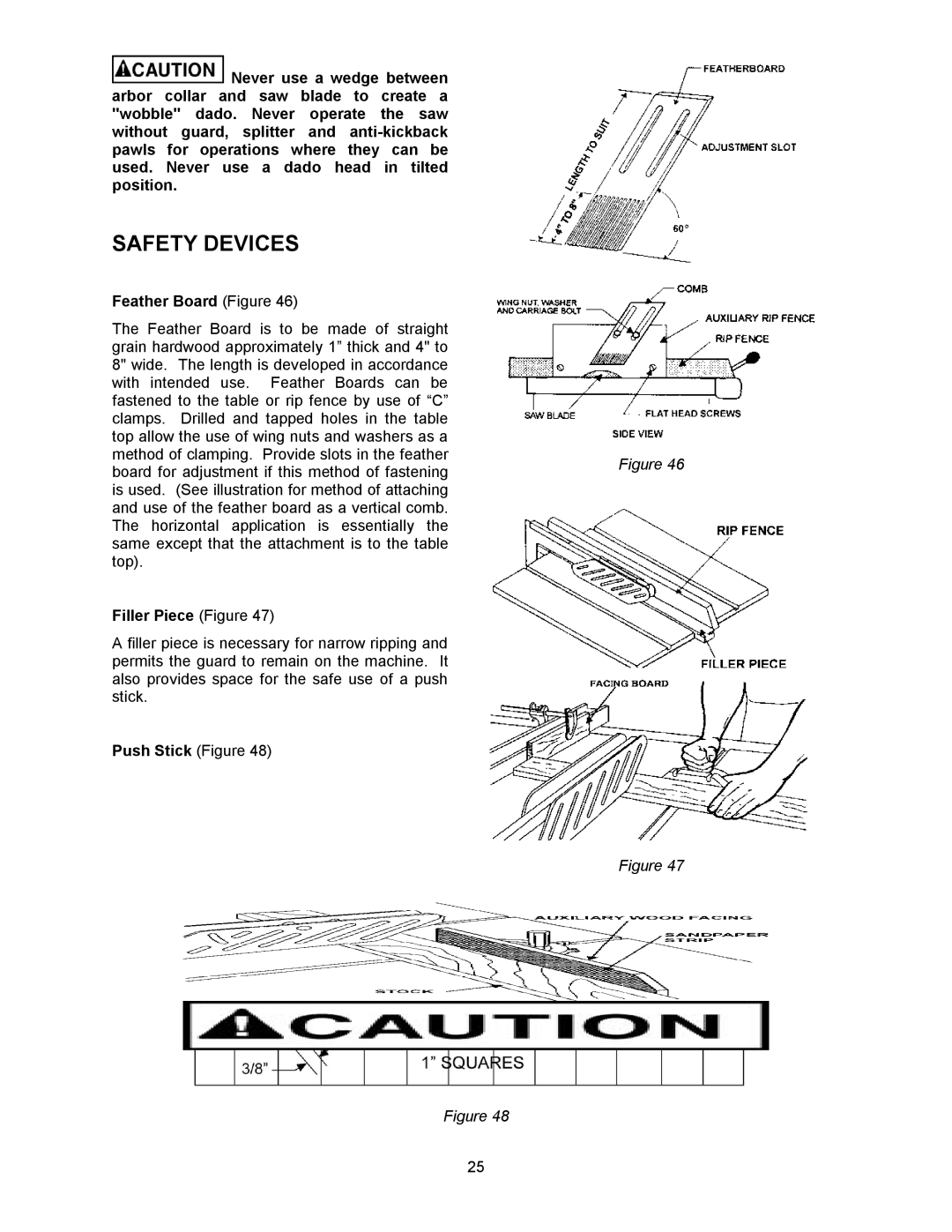
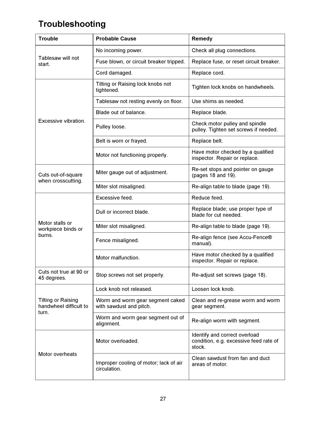
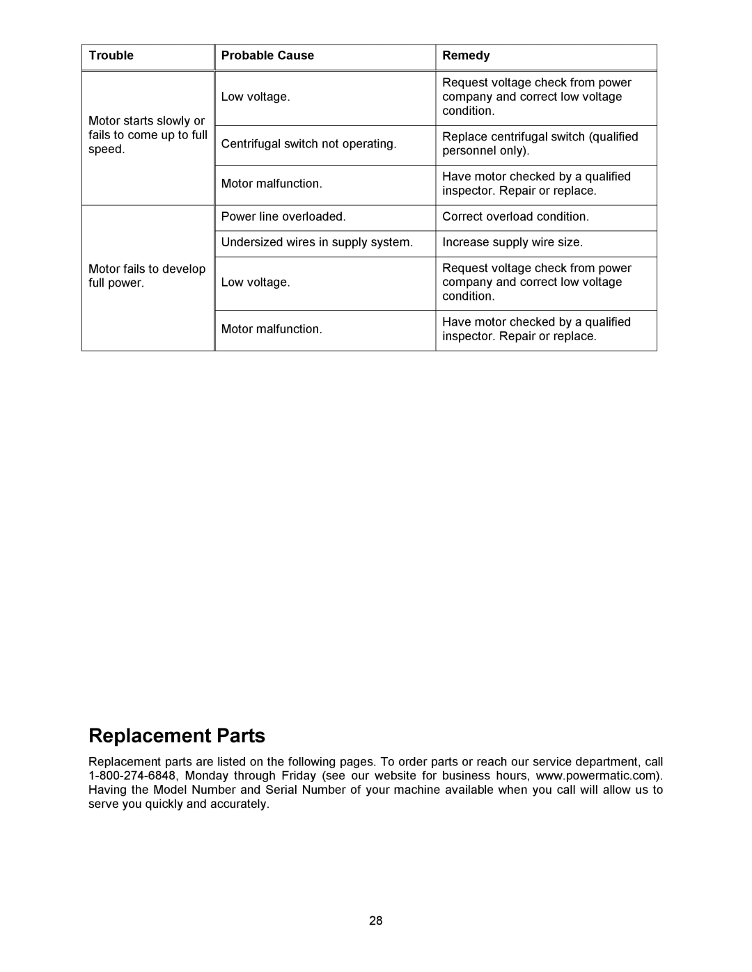
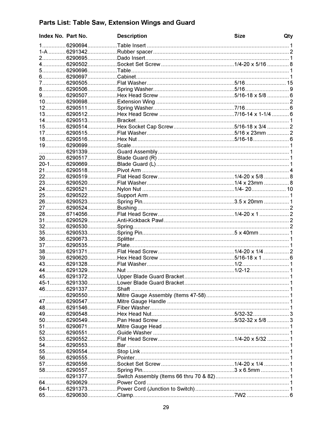
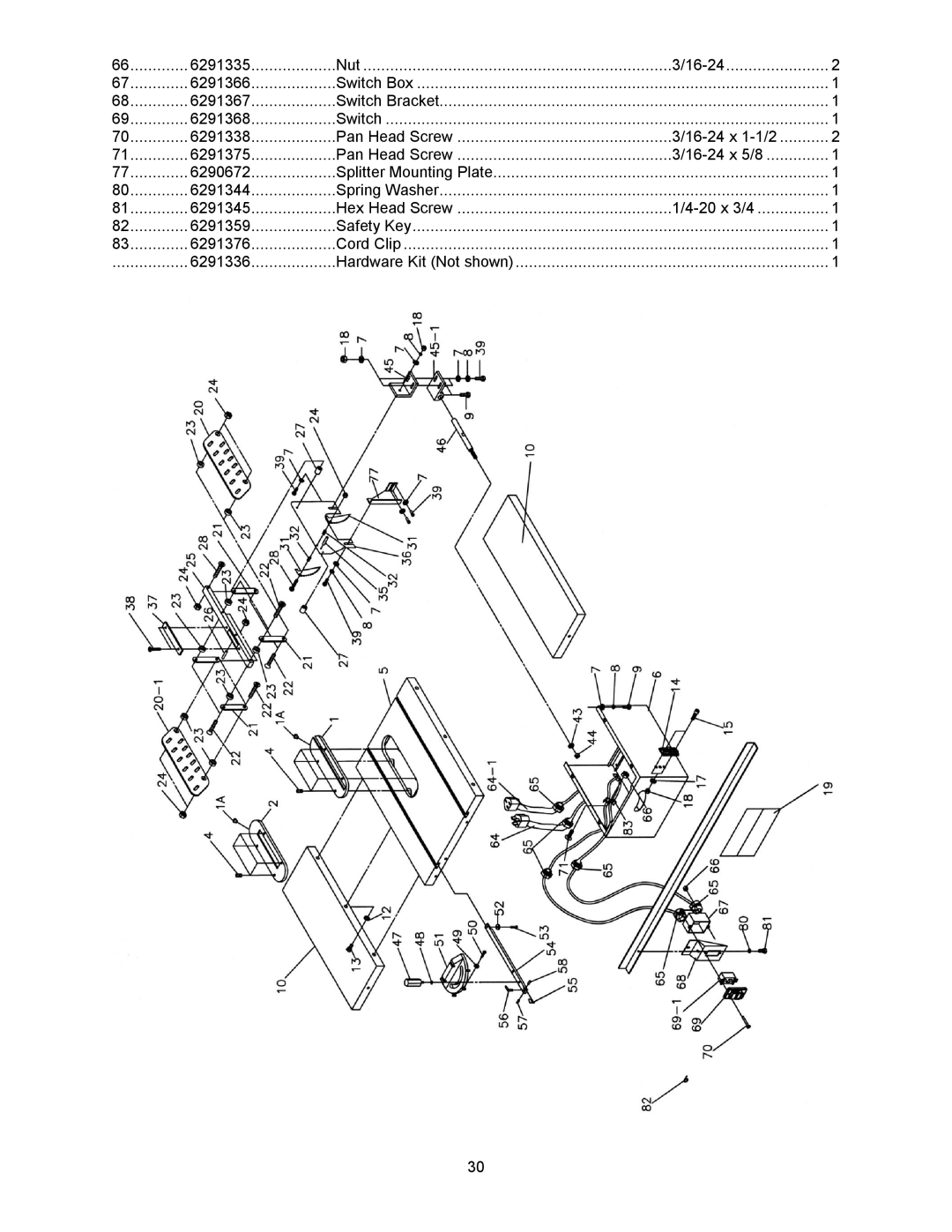
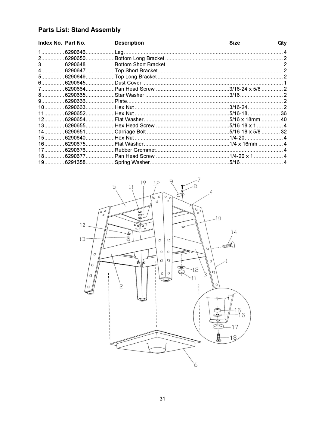
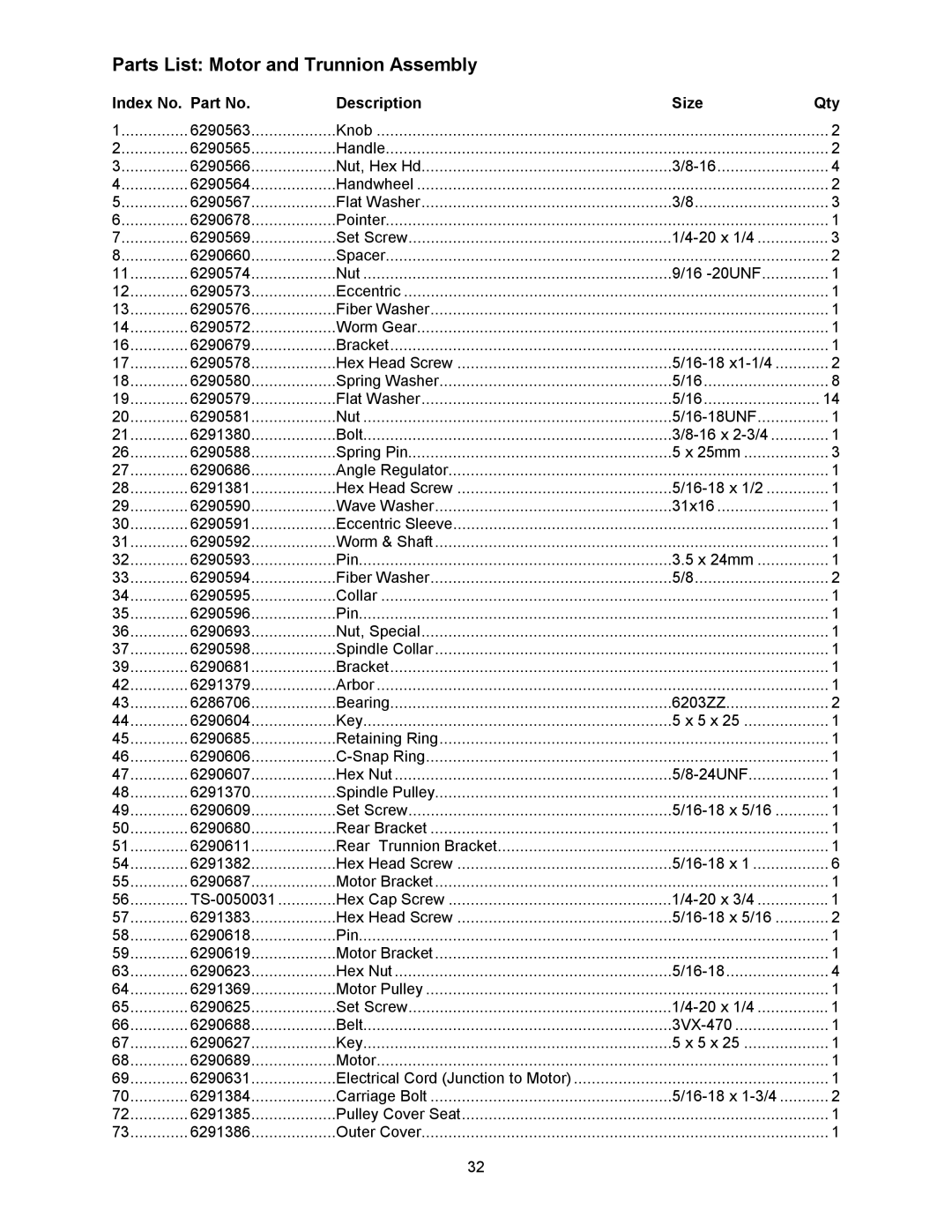
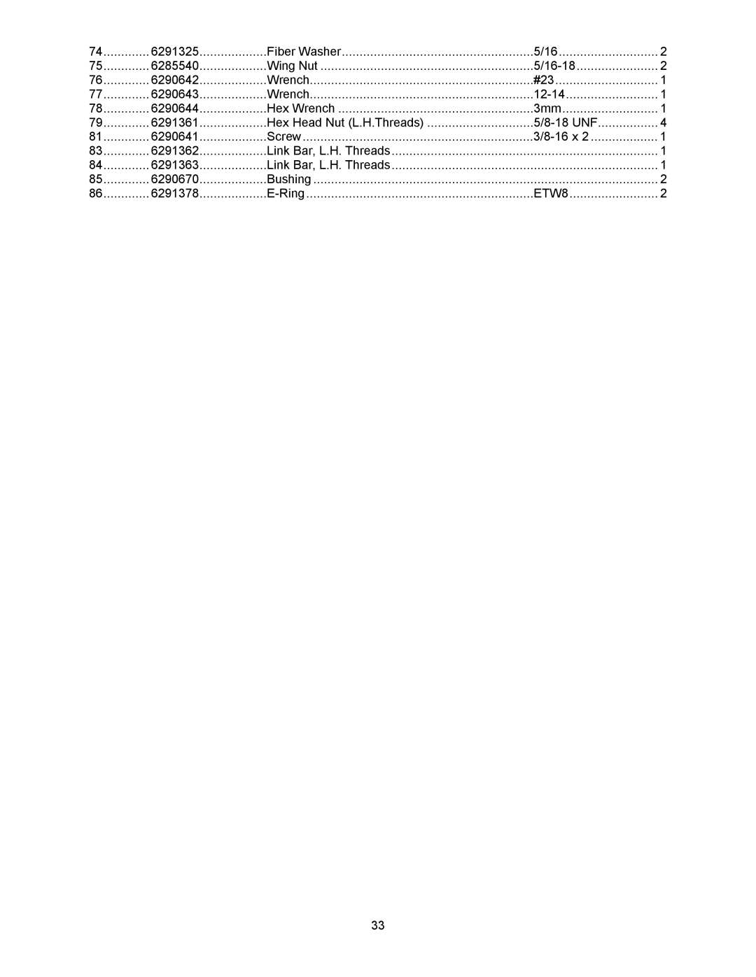
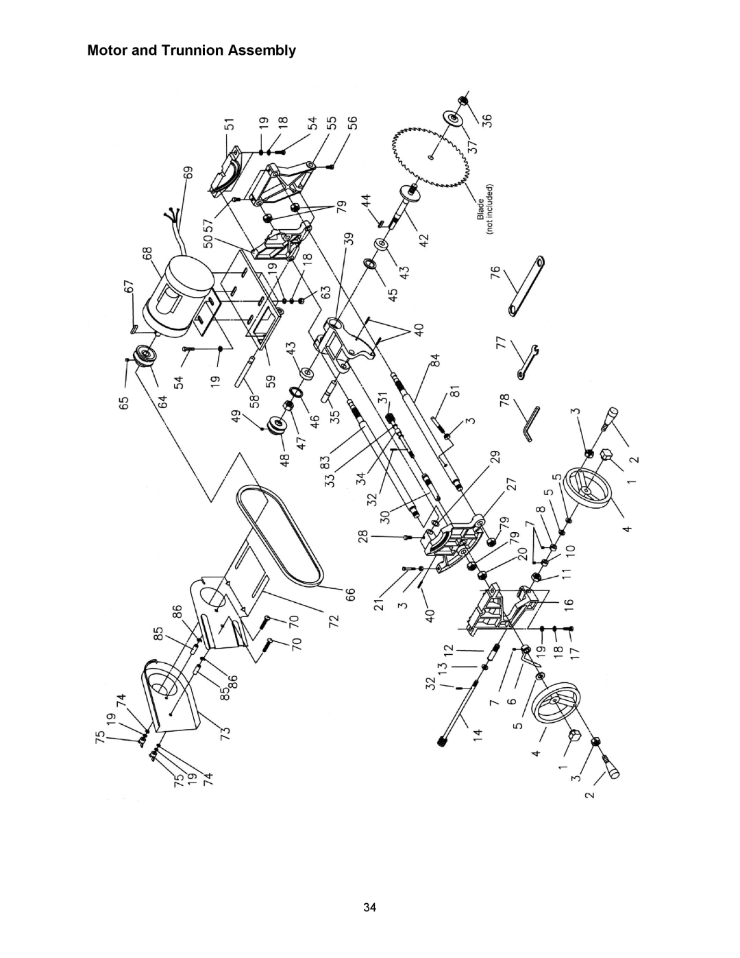
Powermatic 1791228K, 64A operating instructions Mounting Table Insert, Mounting Extension Wings

Page 15

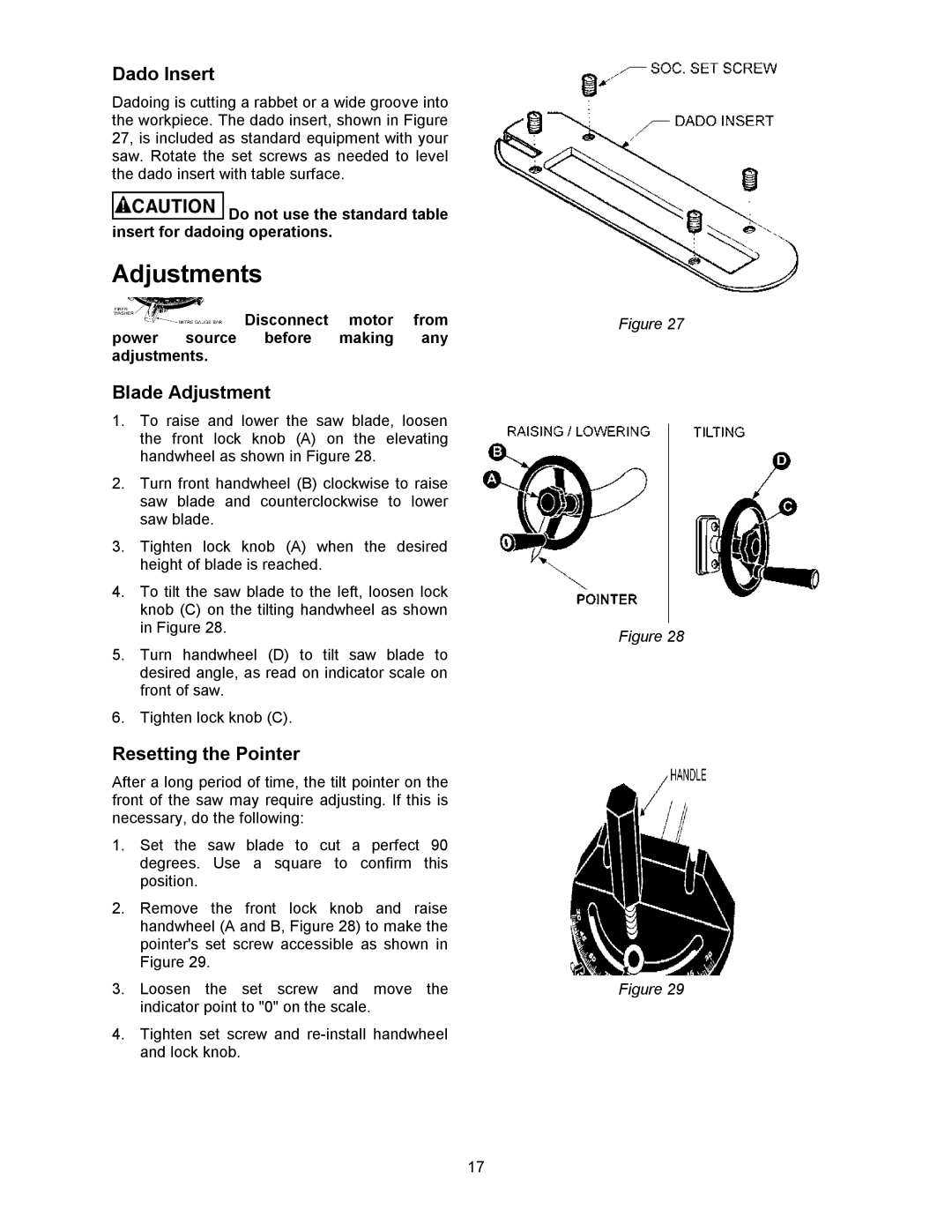
Mounting Table Insert

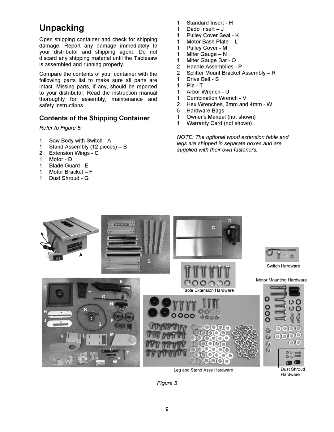
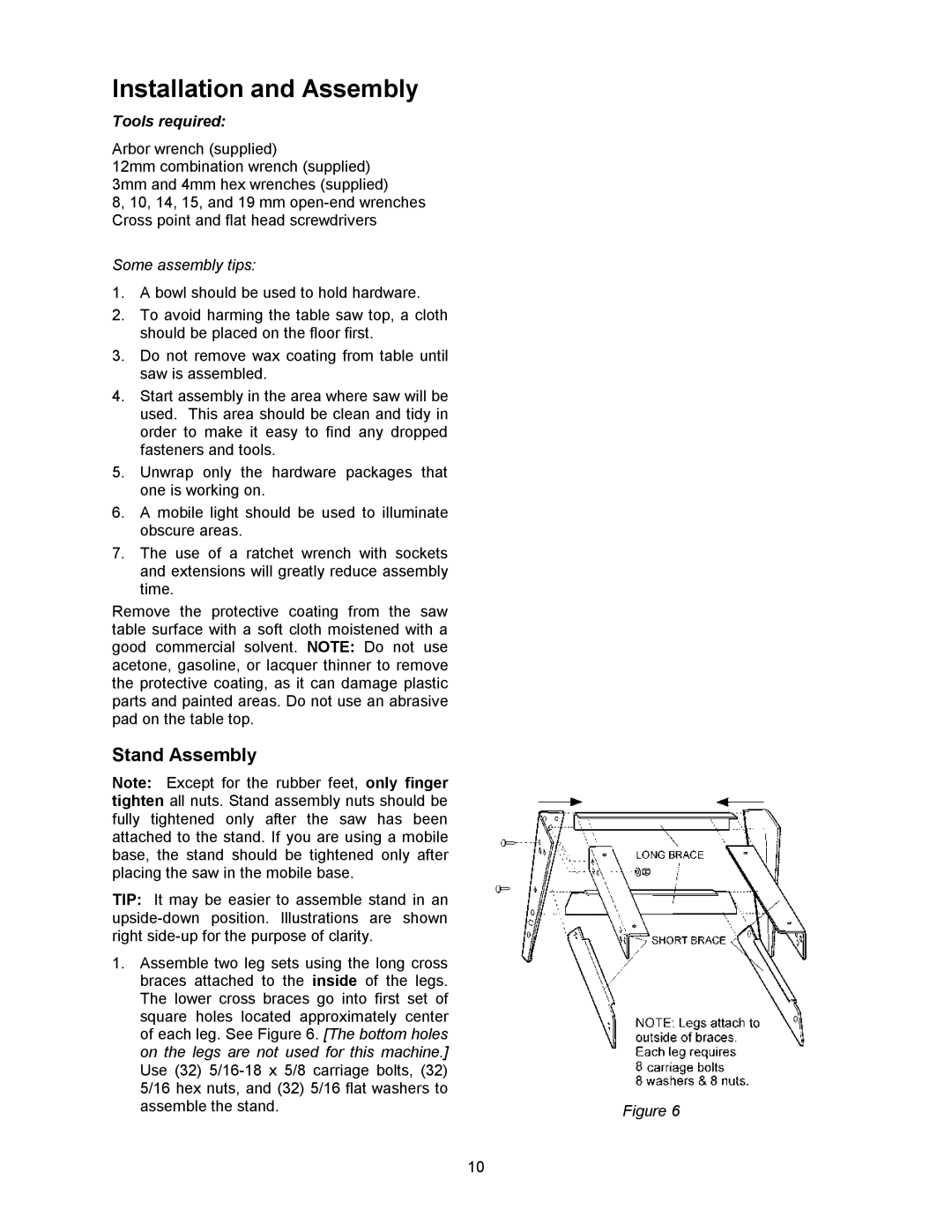
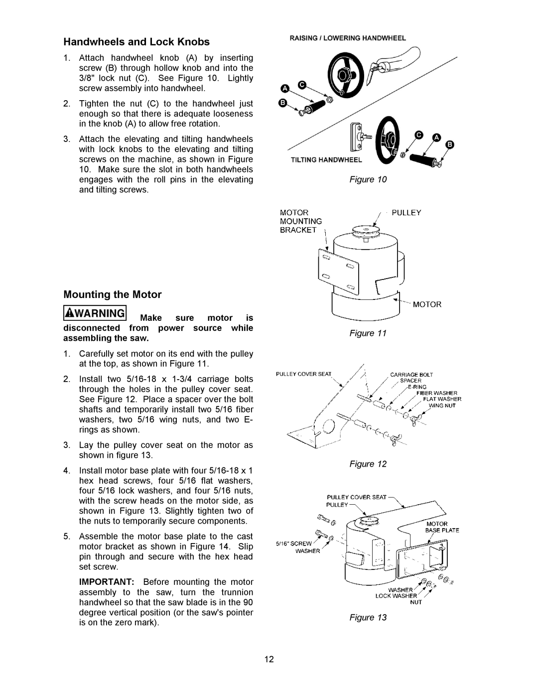
1.Place the table insert into the table opening. With a straight edge, check to see if the insert is level with the surface of the table. See Figure 22.

2.If the insert is not level, correct it by using the straight edge and turning the four set screws in or out until the insert is flush with the table.

Mounting Extension Wings

TIP: Use WD-40® to clean table edges.

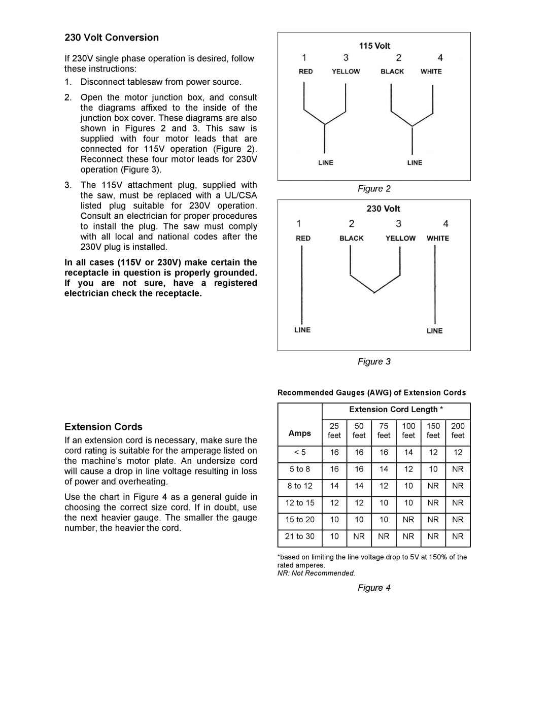
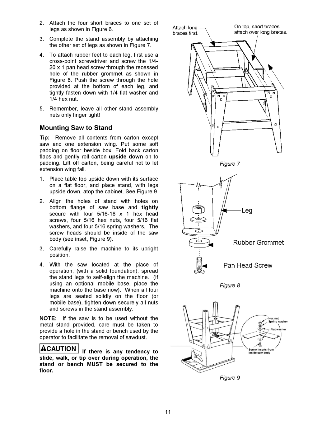
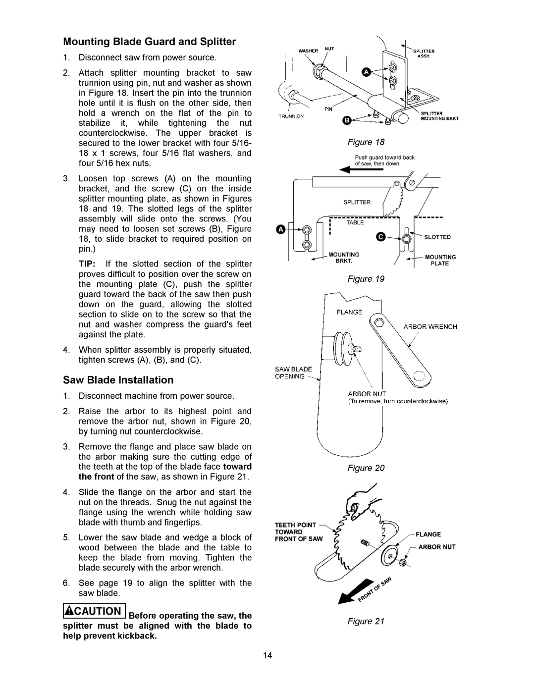
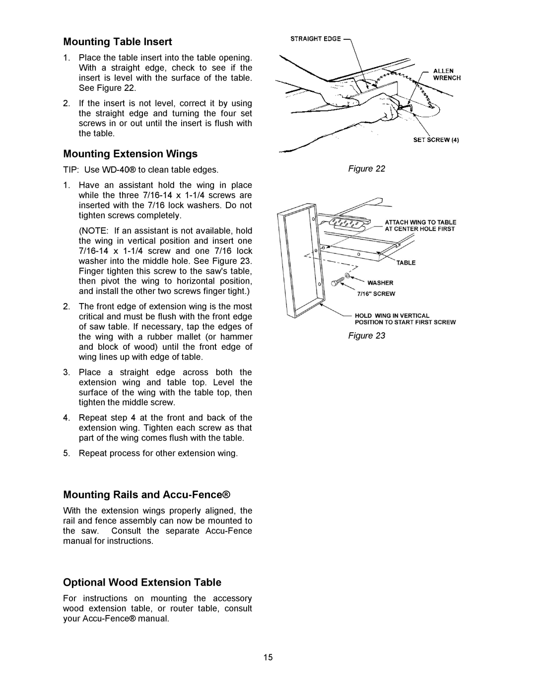
1.Have an assistant hold the wing in place while the three 7/16-14 x 1-1/4 screws are inserted with the 7/16 lock washers. Do not tighten screws completely.

(NOTE: If an assistant is not available, hold the wing in vertical position and insert one 7/16-14 x 1-1/4 screw and one 7/16 lock washer into the middle hole. See Figure 23. Finger tighten this screw to the saw's table, then pivot the wing to horizontal position, and install the other two screws finger tight.)

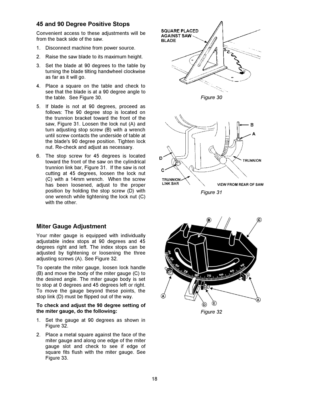
2.The front edge of extension wing is the most critical and must be flush with the front edge of saw table. If necessary, tap the edges of the wing with a rubber mallet (or hammer and block of wood) until the front edge of wing lines up with edge of table.

3.Place a straight edge across both the extension wing and table top. Level the surface of the wing with the table top, then tighten the middle screw.

4.Repeat step 4 at the front and back of the extension wing. Tighten each screw as that part of the wing comes flush with the table.

5.Repeat process for other extension wing.

Mounting Rails and Accu-Fence®

With the extension wings properly aligned, the rail and fence assembly can now be mounted to the saw. Consult the separate Accu-Fence manual for instructions.

Optional Wood Extension Table

For instructions on mounting the accessory wood extension table, or router table, consult your Accu-Fence® manual.

Figure 22

Figure 23

15
Image 15
Contents Part No. M-0460250 WMH Tool GROUP, IncMore Information Warranty and ServiceTable of Contents Page Page Introduction Specifications Grounding Instructions Electrical ConnectionsVolt Conversion Unpacking Contents of the Shipping ContainerStand Assembly Installation and AssemblyMounting Saw to Stand Mounting the Motor Handwheels and Lock KnobsPage Mounting Blade Guard and Splitter Saw Blade InstallationOptional Wood Extension Table Mounting Table InsertMounting Extension Wings Mounting Rails and Accu-FenceMotor Disconnect Plug Installing Dust ShroudInstalling Switch Miter Gauge AssemblyDado Insert AdjustmentsBlade Adjustment Resetting the Pointer90 Degree Positive Stops Miter Gauge AdjustmentAligning Miter Slot to Blade Aligning Splitter to BladeTo minimize or prevent injury from kickbacks Basic Saw OperationRipping Operating ProceduresPage Do not crosscut workpieces shorter than ResawingBevel and Miter Operations Feather Board Figure Filler Piece FigurePush Stick Figure Optional Accessories MaintenanceTroubleshooting TroubleProbable Cause Remedy Trouble Probable Cause Remedy Replacement PartsIndex No. Part No Description Size Qty Parts List Table Saw, Extension Wings and Guard6291335 Parts List Stand Assembly Parts List Motor and Trunnion Assembly ETW8 Motor and Trunnion Assembly Page Vantage Drive Elgin, Illinois Phone