A ![]()
![]()
![]()
Fig. 50
A
Fig. 52
B
Fig. 51
F ![]()
![]() D
D
G
E
Fig. 53
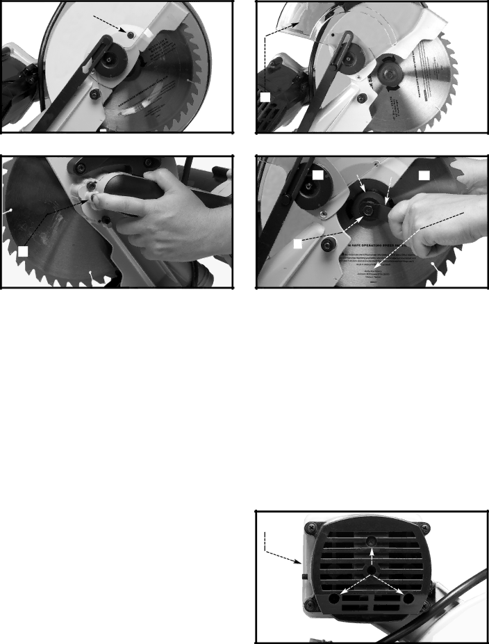
1.Remove the screw (A) Fig. 50 and rotate the cover (B) to the rear (Fig. 51).
2.Depress the arbor lock (A) Fig. 52 to lock the blade.
3.Use the supplied blade changing wrench (D) Fig. 53 to loosen (clockwise) the arbor screw (E).
4.Remove the arbor screw (E), the outside the blade flange (F), and the saw blade (G) from the saw arbor.
5.Place the new blade on the arbor.
![]() Confirm that the teeth of the saw blade are pointing down at the front (See Fig. 51)
Confirm that the teeth of the saw blade are pointing down at the front (See Fig. 51)
6.Place the outside blade flange (F) Fig. 53 on the arbor.
7.Thread the arbor screw into the arbor. Depress the arbor lock and tighten
8.Rotate the blade cover (B) Fig. 51 to the front, and replace the screw (A) Fig. 50 that was removed in STEP 1. Tighten the screw (A) Fig. 50 securely.
BRUSH INSPECTION AND REPLACEMENT
Brush life varies, depending on the load on the motor.
Check the brushes after the first 50 hours of use for a B new machine, or after a new set of brushes has been installed. After the first check, examine them after every
10 hours of use until replacement is necessary. To inspect the brushes:
 D I S C O N N E C T M A C H I N E F R O M POWER SOURCE.
1.Remove the three screws (A) Fig. 54 and remove the motor cover (B).
A
Fig. 54
18