Location
Use the following guidelines to select a suitable location for the unit.
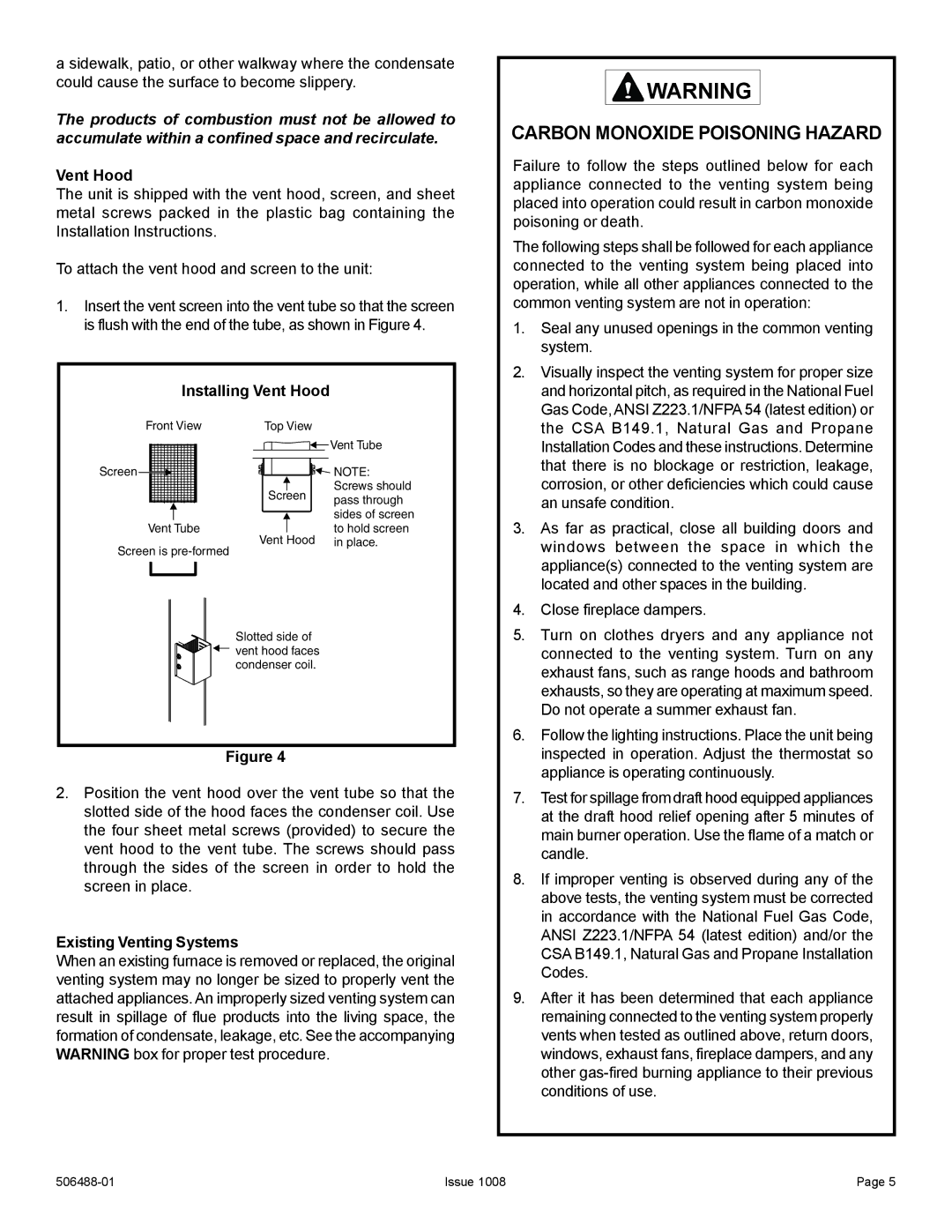
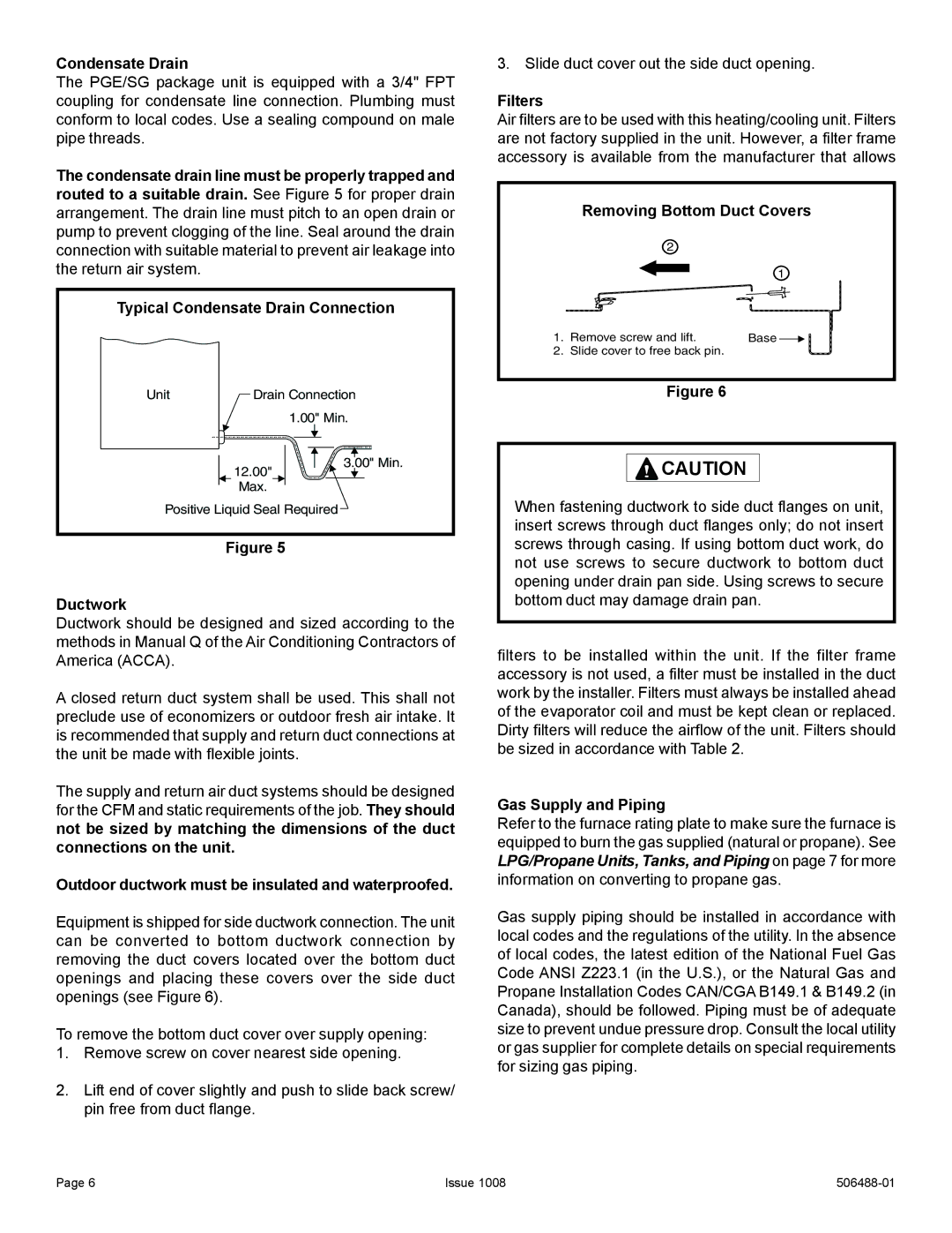
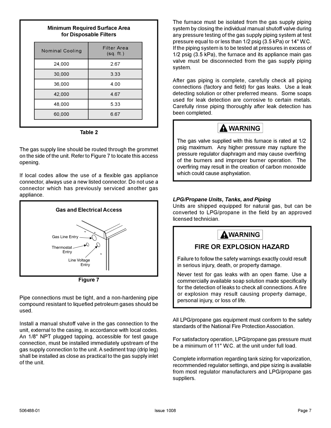
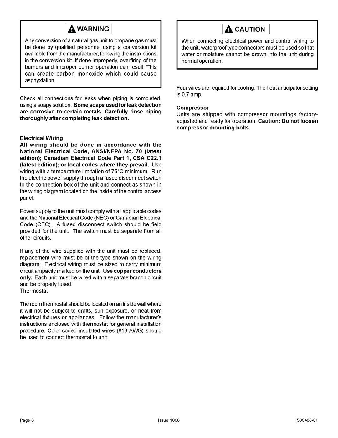
1.Unit is designed for outdoor installation only. Unit must be installed so all electrical components are protected from water.
2.Condenser coils must have an unlimited supply of air.
3.For ground level installation, use a level prefabricated pad or use a level concrete slab. Do not tie the slab to the building foundation.
4.Maintain level within a tolerance of 1/4" maximum across the entire length or width of the unit.
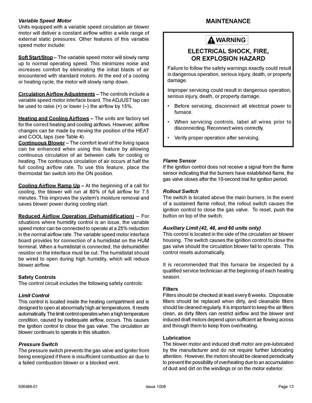
5.Do not locate the unit where the combustion air supply will be exposed to any of the following substances:
•Permanent wave solutions
•Chlorinated waxes and cleaners
•
•Water softening chemicals
•Deicing salts or chemicals
•Carbon tetrachloride
•
•Cleaning solvents (such as perchloroethylene)
•Printing inks, paint removers, varnishes, etc.
•Cements and glues
•Antistatic fabric softeners for clothes dryers
•Masonry acid washing materials
•Chlorinated laundry products
•Hydrochloric acid
Use of unit as a construction heater during any phase of construction is not recommended. Very low return air temperatures, harmful vapors, and operation of the unit with clogged or misplaced filters will damage the unit. However, if the installation and operating conditions specified below are followed, use of this unit for heating of buildings or structures under construction is permissible:
•The vent hood must be installed per these installation instructions.
•A room thermostat must control the furnace. The use of fixed jumpers that will provide continuous heating is not allowed.
•The return air duct must be provided and sealed to the unit.
•Return air temperature must be maintained between 60°F (16°C) and 80°F (27°C).
•Air filters must be installed in the system and must be maintained during construction.
•Air filters must be replaced upon construction completion.
•The input rate and temperature rise must be set per the unit rating plate.
•100% outdoor air must be provided for combustion air requirements during construction. Installation of this unit in its intended outdoor location will accomplish this.
•The heat exchanger, components, duct system, air filter(s), and evaporator coil must be thoroughly cleaned following final construction cleanup.
•Following the final cleaning, all furnace operating conditions (including ignition, input rate, temperature rise, and venting) must be verified according to these instructions.
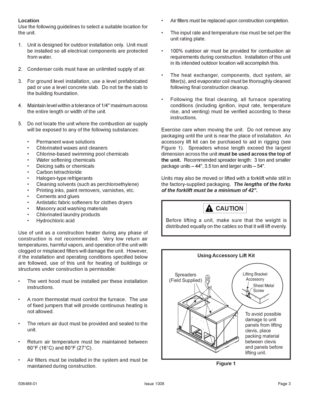
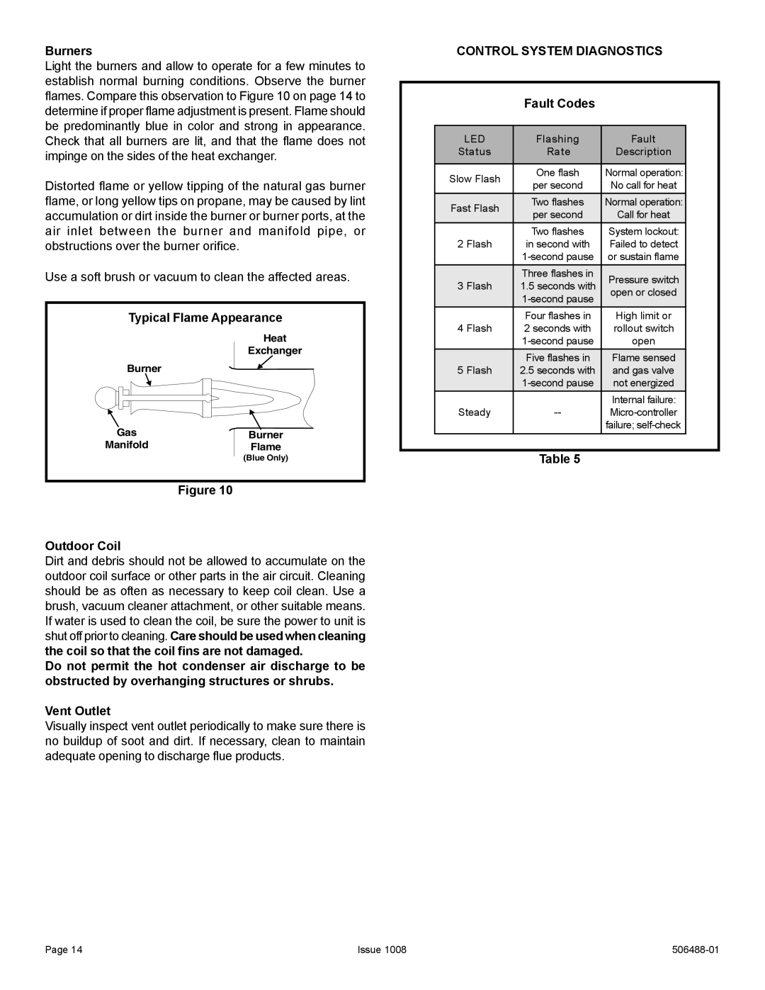
Exercise care when moving the unit. Do not remove any packaging until the unit is near the place of installation. An accessory lift kit can be purchased to aid in rigging (see Figure 1). Spreaders whose length exceed the largest dimension across the unit must be used across the top of the unit. Recommended spreader length: 3 ton and smaller package units – 44", 3.5 ton and larger units – 54".
Units may also be moved or lifted with a forklift while still in the
![]()
![]() CAUTION
CAUTION
Before lifting a unit, make sure that the weight is distributed equally on the cables so that it will lift evenly.
| Using Accessory Lift Kit | |
Spreaders |
| Lifting Bracket |
(Field Supplied) | Accessory | |
| ||
|
| Sheet Metal |
|
| Screw |
To avoid possible damage to unit panels from lifting clevis, place packing material between clevis and panels before lifting unit.
Figure 1
Issue 1008 | Page 3 |
