Hobart Welding Products OM-230 455D manual Sequence Of Piercing Operation

Page 23

.A complete Parts List is available at www.HobartWelders.com

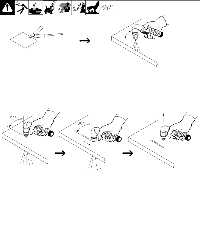
5-6. Sequence Of Piercing Operation

Y The pilot arc starts immediately when trigger is pressed.

Connect work clamp to a clean, paint-free location on workpiece, as close to cutting area as possible.

Hold torch at an angle to

the workpiece. Press trigger. Pilot arc starts.

Move torch to upright

Maintain torch position

Release trigger. Postflow cooling

°

and continue cutting.

continues after releasing trigger.

position 90 to surface.


. Postflow must finish before

Start cutting when arc


pierces workpiece.


trigger will restart pilot arc.


Ref. 803 640-A / 801 400-B

OM-230 455 Page 19

Image 23
Contents File Plasma Cutters OM-230 455DProcesses DescriptionProtect Your Investment From Hobart to YouTable of Contents Page Cutting can cause fire or explosion Symbol UsageMarks a special safety message Plasma Arc Cutting HazardsNoise can damage hearing Exploding Parts can injureFlying Sparks can cause injury ARC Rays can burn eyes and skinCalifornia Proposition 65 Warnings About Pacemakers Principal Safety StandardsEMF Information Identifie un message de sécurité particulier Signification des symbolesLE Coupage présente un risque de feu ou d’explosion UNE Décharge Électrique peut entraîner la mortLE Plasma D’ARC peut entraîner des blessures Risque de blessure en casLE Bruit peut endommager l’ouïe LES Fumées ET LES GAZ peuvent être dangereuxRisque D’INCENDIE OU DES Pieces Chaudes peuvent pro- voquer des brûlures gravesDES Organes Mobiles peuvent provoquer des blessures LA Chute DE L’APPAREIL peut blesserConsignes relatives aux stimulateurs cardiaques Principales normes de sécuritéInformation sur les champs électromagnétiques LE Coupage à L’ARC peut causer des interférenceI1eff − DefinitionsI1max Duty Cycle And Overheating − InstallationSpecifications For Power Source Specifications For TorchMovement, Location And Airflow Torch Dimensions And WeightDimensions And Weight Selecting a LocationExtension Cord Data Connecting Work ClampElectrical Service Guide For 120 VAC Plug From Unit Connecting Input PowerGenerator Or Inverter Requirements Check input voltage available at site Grounded ReceptacleElectrode Wrench Cable Management StrapRecommended Cutting Speed For Material Thickness − OperationControls Maintain approximately a 90 angle to Plasma Cutting System PracticesExample Of Cutting Operation When trigger is pressedSequence Of Cutting Operation Pilot arc starts immediatelySplit section to bottom 16 in 1.6 mm Sequence Of Cutting Using Stand-off GuideExample Of Cutting Using Stand-off Guide Sequence Of Piercing Operation Routine Maintenance − Maintenance & TroubleshootingChecking Torch Shield Cup Shutdown System Trouble Lights And Checking Shield Cup Shutdown SystemElectrode Wrench Turn Off power source before checking torch partsChecking/Replacing Retaining Cup, Tip, And Electrode Disconnect input power Compressor Filter Cleaning And ReplacementWork Cable Connections Torch And Work Cable ConnectionsTorch Connections Check Control board PC1 Troubleshooting Power SourceOnly by authorized Service Station Troubleshooting Torch Circuit Diagram − Electrical DiagramRecommended Spare Parts − Parts ListRecommended Spare Parts Material Thickness Gauge Page Assistance ServiceSupport Hobart Welding Products Contact your Distributor for