HP G6 B9P54UA manual Component replacement procedures

Page 79

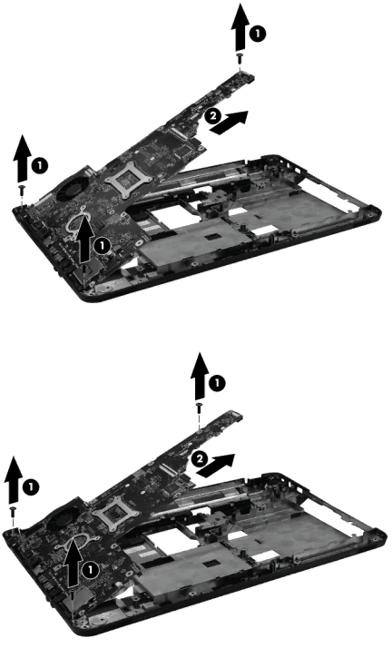
5.Lift the system board (2) from the right edge and pull it away from the base enclosure at an angle. For AMD computer models, see the following image.

For Intel computer models, see the following image.

When replacing the system board, be sure that the following components are removed from the defective system board and installed on the replacement system board:

Fan/heat sink assembly (see Fan/heat sink assembly on page 73)

Processor (see Processor on page 77)

Component replacement procedures

71

Image 79
Contents HP Pavilion G6 Notebook PC Page Safety warning notice Iv Safety warning notice Table of contents Specifications Power cord set requirements Viii HP Pavilion G6 Notebook PC Processors Product descriptionCategory Description Intel 2nd Intel Previous Generation DiscreteGeneration Discrete UMA Product descriptionGraphics ChipsetMemory PanelHard drives Ethernet Optical drivesWebcam AudioMedia card PowerOperating Preinstalled System ExternalServiceability End-user replaceable parts Component Description External component identificationTop TouchPadLights Button Control Panel System and Security PowerKeys FrontComponent Description Speakers Produce sound Right side Left side External component identification Cyberlink YouCam DisplayBottom Serial number location Illustrated parts catalogIllustrated parts catalog Computer major componentsUSB board Power connector includes cablePower button board Speaker assembly includes cableDescription Spare part number Item Description Spare part number Wlan module Base enclosureHard drive Battery Hard drive connector boardDisplay assembly components Display Screw Kit not illustrated Description Spare part number Hard drive Mass storage devicesOptical Drive protective insert Thermal pads kit Power cord, AC, 3 wire, black, 1.83-mMiscellaneous parts Description Spare part number AC adaptersSpare part number Description Sequential part number listingIllustrated parts catalog Sequential part number listing Illustrated parts catalog Sequential part number listing Tools required Removal and replacement proceduresPreliminary replacement requirements Service considerationsCables and connectors Electrostatic discharge damage Grounding guidelinesPackaging and transporting guidelines Material Use Voltage protection level Equipment guidelinesSerial number Component replacement proceduresDescription Spare part number Rubber Feet Kit 639572-001 Computer feetBattery Service door Hard drive Page Optical drive Page Wlan module Page Memory module RTC battery Keyboard Page Top cover Page Page Page Description Spare part number Power button board 640884-001 Power button boardSpeaker assembly TouchPad button board Description Spare part number USB board 640883-001 USB boardSecurity cable lock Power connector Display assembly Page Page Page Page Page System board Page Component replacement procedures Page Fan/heat sink assembly Page Page Page Processor Description Spare part number Page Computer specifications Specifications39.6-cm 15.6-in display specifications Hard drive specifications Cache buffer Data transfer rate Random access timeTransfer mode Applicable discBD-ROM Changing the language of Setup Utility Setup Utility BiosStarting Setup Utility Using Setup UtilityExiting Setup Utility Restoring factory default settings in Setup UtilityDisplaying system information Determining the Bios version Updating the BiosDownloading a Bios update Page Restore Backup and recoveryCreating restore media Performing a system restore Restoring using the restore media Changing the computer boot order Backing up and recovering your informationUsing Windows Backup and Restore When to create restore points Using Windows system restore pointsRequirements for all countries Power cord set requirementsCountry/region Accredited agency Applicable note number Requirements for specific countries and regionsRequirements for specific countries and regions Recycling Index BiosJacks Removal/replacement