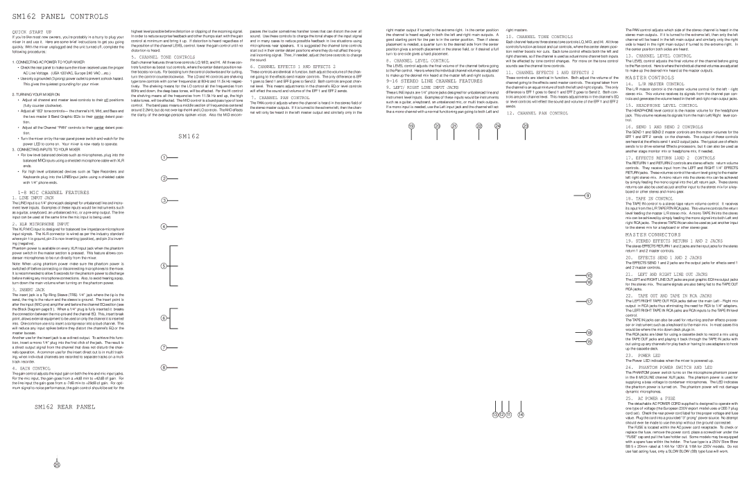
Carvin SM162 Channel Tone Controls, Channel Effects 1 and Effects, Channel PAN Control, Power LED

Page 3

SM162 PANEL CONTROLS

QUICK START UP

If you’re like most new owners, you’re probably in a hurry to plug your mixer in and use it. Here are some brief instructions to get you going quickly. With the mixer unplugged and the unit turned off, complete the following procedures:

1. CONNECTING AC POWER TO YOUR MIXER

• Check the rear panel to make sure the mixer received uses the proper

AC Line Voltage. (USA 120VAC, Europe 240 VAC ...etc.)

• Use only a grounded (3 prong) power outlet to prevent a shock hazard.

This gives the quietest grounding for your mixer.

2. TURNING YOUR MIXER ON

• Adjust all channel and master level controls to their off positions

(fully counter clockwise).

• Adjust all “EQ” tone controls— the channel’s Hi, Mid, and Bass and

the two master 9 Band Graphic EQ’s to their center detent posi-

tion.

highest level possible before distortion or clipping of the incoming signal. In order to reduce surprise feedback and other thumps start with the gain control at minimum and bring it up. If distortion is heard regardless of the position of the channel LEVEL control, lower the gain control until no distortion is heard.

5. CHANNEL TONE CONTROLS

Each channel features three tone controls LO, MID, and HI. All three con- trols function as boost /cut controls, where the center detent position nei- ther boosts nor cuts. For boosting turn the control clockwise and for cutting, turn the control counterclockwise. The LO and HI controls are shelving type tone controls with corner frequencies at 80Hz and 11.5k Hz respec- tively. The shelving means for the LO control all the frequencies from 80Hz and down, the deep bass tones, will be effected. For the HI control the shelving means all the frequencies from 11.5k Hz and up, the high treble tones, will be effected. The MID control is a band pass type of tone control. The band pass means a middle section of frequencies centered around 2.2kHz, but do not over-lap the HI and LO controls. The MID affects the clarity of the average persons spoken voice. Also the MID encom-

passes the louder sometimes harsher tones that can distort the over all sound. Use these controls to change the tonal shape of the input signal and in many cases to reduce possible feedback in live situations using microphones near speakers. It is suggested the channel tone controls start out in their center detent positions where they do not affect the orig- inal incoming signal. Then, if needed, adjust the tone controls to change the sound.

6. CHANNEL EFFECTS 1 AND EFFECTS 2

These controls are identical in function, both adjust the volume of the chan- nel going to the effects send master controls. The only difference is EFF 1 goes to Send 1 and EFF 2 goes to Send 2. Both controls are post chan- nel level. This means adjustments in the channel’s EQ or level controls will effect the sound and volume of the EFF 1 and EFF 2 sends.

7. CHANNEL PAN CONTROL

The PAN control adjusts where the channel is heard in the stereo field of the stereo master outputs. If it is turned to the extreme left, then the chan- nel will only be heard in the left master output and similarly only in the

right master output if turned to the extreme right. In the center position the channel is heard equally in both the left and right main outputs. A good starting point for the pan is in the center position. Then if stereo placement is needed, a quarter turn to the desired side from the center position gives a smooth placement in the stereo field, or if desired a full turn to one side gives a hard placement.

8. CHANNEL LEVEL CONTROL

The LEVEL control adjusts the final volume of the channel before going to the Pan control. Here is where the individual channel volumes are adjusted to make up the desired mix heard at the master left and right outputs.

9-16 STEREO LINE CHANNEL FEATURES

9. LEFT/ RIGHT LINE INPUT JACKS

These LINE inputs are 1/4” phone jacks designed for unbalanced line and instrument level inputs. Examples of these inputs would be instruments such as a guitar, a keyboard, an unbalanced mic, or multi track outputs. If a mono input is needed, use the Left input jack and the channel will act like a mono channel with a normal functioning pan going to both Left and

right masters.

10. CHANNEL TONE CONTROLS

Each channel features three stereo tone controls LO, MID, and HI. All three controls function as boost and cut controls, where the center detent posi- tion neither boosts nor cuts. Each tone control effects both the left and right channels, so if the channel is used as a dual mono channel both inputs will be effected by tone control changes. For more on the tone control sounds see the channel tone controls.

11. CHANNEL EFFECTS 1 AND EFFECTS 2

These controls are identical in function. Both adjust the volume of the channel going to the effects send master controls. The signal taken from the channel is an equal mixture of both the left and right signals. The only difference is EFF 1 goes to Send 1 and EFF 2 goes to Send 2. Both con- trols are post channel level. This means adjustments in the channel’s EQ or level controls will effect the sound and volume of the EFF 1 and EFF 2 sends.

12. CHANNEL PAN CONTROL

The PAN control adjusts which side of the stereo channel is heard in the stereo main outputs. If it is turned to the extreme left, then only the left channel will be heard in the left main output and similarly only the right side is heard in the right main output if turned to the extreme right. In the center position both sides are heard.

13. CHANNEL LEVEL CONTROL

The LEVEL control adjusts the final volume of the channel before going to the Pan control. Here is where the individual channel volumes are adjusted to make up the desired mix heard at the master outputs.

MASTER CONTROLS

14.L/R MASTER CONTROL

The L/R master control is the master volume control for the left - right stereo mix. This volume receives its signals from the channel pan con- trols and generates the volume heard in the left and right main output jacks.

15. HEADPHONE LEVEL CONTROL

The HEADPHONE level control is the master volume for the headphone jack. This volume receives its signals from the main Left/Right level con- trol.

• Adjust all the Channel “PAN” controls to their center detent posi-

19

20

21

22

24

23

16. SEND 1 AND SEND 2 CONTROLS


tion.

• Turn the mixer on by the rear panel power switch and watch for the


power LED to come on. Your mixer is now ready to operate.

3. CONNECTING INPUTS TO YOUR MIXER

For low level balanced devices such as microphones, plug into the


balanced MIC inputs using a shielded microphone cable with XLR


ends.

For high level unbalanced devices such as Tape Recorders and


Keyboards plug into the LINE input jacks using a shielded cable


with 1/4” phone ends.

1-8 MIC CHANNEL FEATURES

1. LINE INPUT JACK

The LINE input is a 1/4” phone jack designed for unbalanced line and instru- ment level inputs. Examples of these inputs would be instruments such as a guitar, a keyboard, an unbalanced mic, or a pre-amp output. The line input can be used at the same time the mic input is being used.

2. XLR MICROPHONE INPUT

The XLR MIC input is designed for balanced low impedance microphone input signals. The XLR connector is wired as per the industry standard where pin 1 is ground, pin 2 is non-inverting (positive), and pin 3 is invert- ing (negative).

Phantom power is available on every XLR input jack when the phantom power switch in the master section is pressed. This feature allows con- denser microphones to be run directly from the mixer.

Note: When using phantom power make sure the phantom power is switched off before connecting or disconnecting microphones to the mixer. It is recommended to allow 5 seconds for the phantom power to discharge before making any microphone connections. Also, to avoid hearing a pop, turn down the main volume when turning on the phantom power.

3. INSERT JACK

The insert jack is a Tip Ring Sleeve (TRS) 1/4” jack where the tip is the send, the ring is the return and the sleeve is ground. The insert point is after the input (MIC-pre) amplifier and before the channel EQ section (see the Block Diagram page 9 ). When a 1/4” plug is fully inserted it breaks the connection between the mic-pre and the channel EQ. This, insert break point, allows external equipment to be used on only the channel it is inserted into. One common use is to insert a compressor into a loud channel. This will reduce any input spikes before they distort the channel’s EQ or the master busses.

Another use for the insert jack is as a direct output. To achieve this func- tion, insert a mono 1/4” plug into the first click of the jack. The result is a direct output signal from the channel that does not disturb the chan- nels operation. A common use for the insert direct out is in multi track- ing, when individual channels are recorded to separate tracks on a multi track recorder.

4. GAIN CONTROL

The gain control adjusts the input gain on both the line and mic input jacks. For the mic input, the gain goes from a +4dB min to +42dB of gain. For the line input the gain goes from a -7dB min to +29dB of gain. For opti- mum signal to noise performance, the gain control should be set for the

SM162 REAR PANEL

SM162

1

2

3

4

5

6

7

8

9

10

16

17

18

15

13 12

11

14

The SEND 1 and SEND 2 master controls are the master volumes for the EFF 1 and EFF 2 sends on the channels. The output of these controls are heard at the effects send 1 and 2 output jacks. The typical use of effects sends is to drive external Effects processors, but it can also be used as another stage monitor mix or headphone mix, if needed.

17. EFFECTS RETURN 1AND 2 CONTROLS

The RETURN 1 and RETURN 2 controls are stereo effects return volume controls. They receive input from the LEFT and RIGHT 1/4” EFFECTS RETURN jacks. These volumes control the return level going to the master left right stereo mix. A mono return into the stereo mix can be achieved by simply feeding the mono signal into the Left return jack. These stereo returns can also be used as just another input to the stereo mix for a key- board or other stereo and mono gear.

18. TAPE IN CONTROL

The TAPE IN control is a stereo tape return volume control. It receives its input from the L/R TAPE RTN RCA jacks. This volume controls the return level feeding the master L/R stereo mix. A mono TAPE IN into the stereo mix can be achieved by simply feeding the mono signal into both Left and right RCA jacks. The stereo TAPE IN can also be used as just another input to the stereo mix for a keyboard or other stereo gear.

MASTER CONNECTORS

19. STEREO EFFECTS RETURN 1 AND 2 JACKS

The stereo EFFECTS RETURN 1 and 2 jacks are the input jacks for the stereo return 1 and 2 master controls.

20.EFFECTS SEND 1 AND 2 JACKS

The EFFECTS SEND 1 and 2 jacks are the output jacks for effects send 1 and 2 master controls.

21.LEFT AND RIGHT LINE OUT JACKS

The LEFT and RIGHT LINE OUT jacks are post graphic EQ line output jacks for the stereo mix. The same signals are also being fed to the TAPE OUT RCA jacks.

22.TAPE OUT AND TAPE IN RCA JACKS

The LEFT/RIGHT TAPE OUT RCA jacks deliver the main Left - Right mix output in RCA jacks thus eliminating the need for RCA to 1/4” adapters. The LEFT/RIGHT TAPE IN RCA jacks are RCA inputs to the TAPE IN level control.

The TAPE IN jacks can also be used for returning another effects proces- sor or instrument such as a keyboard to the main mix. In most cases this would be where the mix down deck plugs in.

The RCA jacks are Ideal for using a cassette deck to record a mix using the TAPE OUT jacks and playing it back through the TAPE IN jacks with out using up any channels for play back or having to use adapters to hook up the cassette deck.

23.POWER LED

The Power LED indicates when the mixer is powered up.

24.PHANTOM POWER SWITCH AND LED

The PHANTOM power switch turns on the microphone phantom power in the 8 MIC/LINE channel XLR jacks. The phantom power is used for supplying a bias voltage to condenser microphones. The LED indicates the phantom power is turned on. The phantom power will not damage dynamic microphones.

25.AC POWER & FUSE

The detachable AC POWER CORD supplied is designed to operate with one type of voltage (the European 230V export model uses a CEE-7 plug cord set). Check the rear power cord label for the proper voltage and fuse value. Plug the cord into a grounded “3” prong” power source. No attempt should ever be made to use the amp without the ground connected.

The FUSE is located within the AC power cord receptacle. To check or replace the fuse, remove the power cord, place a screwdriver under the “FUSE” cap and pull the fuse holder out. Some models may be equipped with a spare fuse within the holder. The fuse type is a 250V Slow Blow SB 5 x 20mm rated at 1/4A for 120V & 1/8A for 230V models. Do not use fast acting fuse, only a SLOW BLOW (SB) type fuse will work.
25

Image 3
Contents Micro Toroid Supply Internal Signal Routing with no RFModel SM162 Specifications Channel OverviewHalf Insert Connecting Speakers & Power AmplifiersFull Insert Eight Track SystemChannel Tone Controls Power LEDPhantom Power Switch and LED AC Power & Fuse

SM162 specifications

The Carvin SM162 is a professional-grade live sound mixer that is designed to provide users with a versatile and high-quality audio experience. With its compact size and robust construction, it is particularly well-suited for smaller venues, mobile rigs, and home studios.

One of the standout features of the SM162 is its impressive 16-channel configuration, allowing for numerous inputs and outputs to accommodate various audio sources. Each channel is equipped with a 3-band equalizer, giving users precise control over their sound. This includes high, mid, and low frequency adjustments, enabling users to shape their audio to perfection. The mixer also offers individual gain controls, which helps to ensure that each channel can be fine-tuned for optimal performance.

Another notable aspect of the SM162 is its built-in effects section, which offers a range of studio-quality reverb and delay effects. This feature allows users to add ambience and depth to their mix, enhancing overall audio quality without the need for external processing equipment. Additionally, the mixer comes with a phantom power supply, making it compatible with condenser microphones, which require additional power to operate effectively.

The SM162 also provides flexible routing options, including main and monitor outputs, making it easy to set up for live performances, recording sessions, or practice environments. The inclusion of a 7-band graphic equalizer on the main output allows for further refinement of the overall sound, ensuring that the mix translates well across different playback systems.

Durability is a key characteristic of the Carvin SM162. Constructed with high-quality materials that can withstand the rigors of transport and frequent use, this mixer is built to last. Its intuitive layout, paired with illuminated controls, allows for easy operation in low-light environments, making it ideal for live settings.

In summary, the Carvin SM162 mixer combines an array of essential features with advanced technology, catering to the needs of audio professionals and enthusiasts alike. Its combination of quality sound processing, versatile input options, and durable design makes it a reliable choice for any live sound application.